
Electromagnetic fuel injection valve

A fuel injection valve, electromagnetic technology, applied in the direction of fuel injection devices, charging systems, engine components, etc., can solve the problems of valve closing characteristics deviation, poor centering, etc., to achieve stable opening and closing posture, ensure centering, improve The effect of magnetic responsiveness

Active Publication Date: 2008-04-09
HITACHI ASTEMO LTD
View PDF9 Cites 0 Cited by
  • Summary
  • Abstract
  • Description
  • Claims
  • Application Information

AI Technical Summary

Problems solved by technology

Because the valve part is conical, the centering property is poor, and the valve closing characteristic will vary.

Method used


Image

  • Electromagnetic fuel injection valve
  • Electromagnetic fuel injection valve
  • Electromagnetic fuel injection valve

Examples


Embodiment Construction

[0040] Hereinafter, an embodiment of the present invention will be described based on a first embodiment of the present invention with reference to the drawings.

[0041] Preferred embodiments of the present invention will be described below with reference to the accompanying drawings.

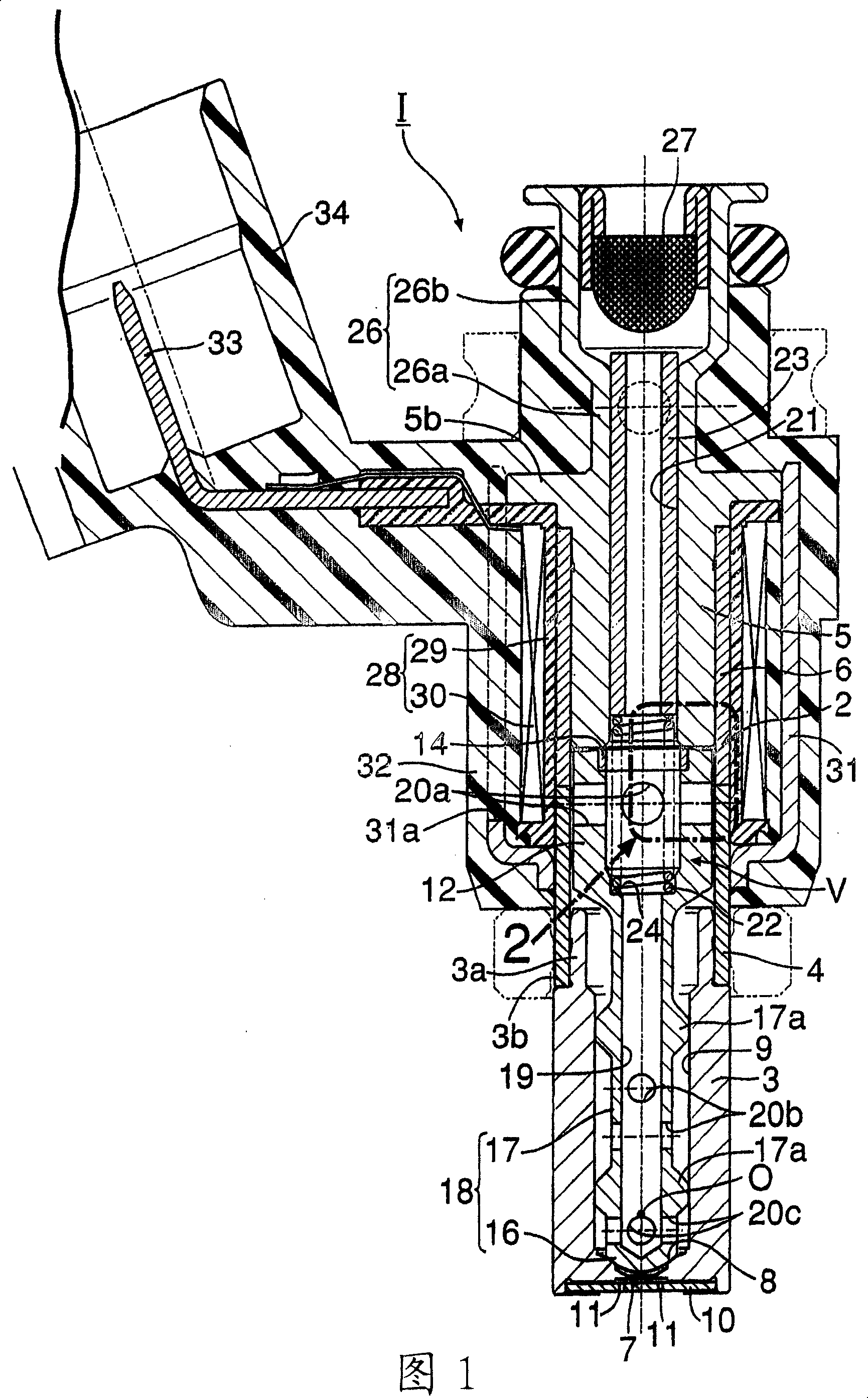
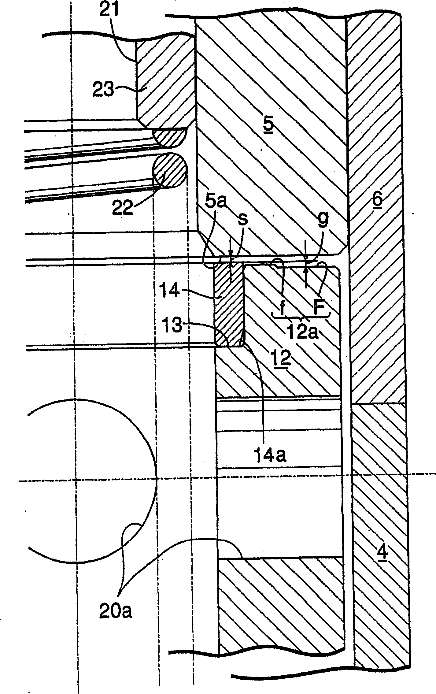
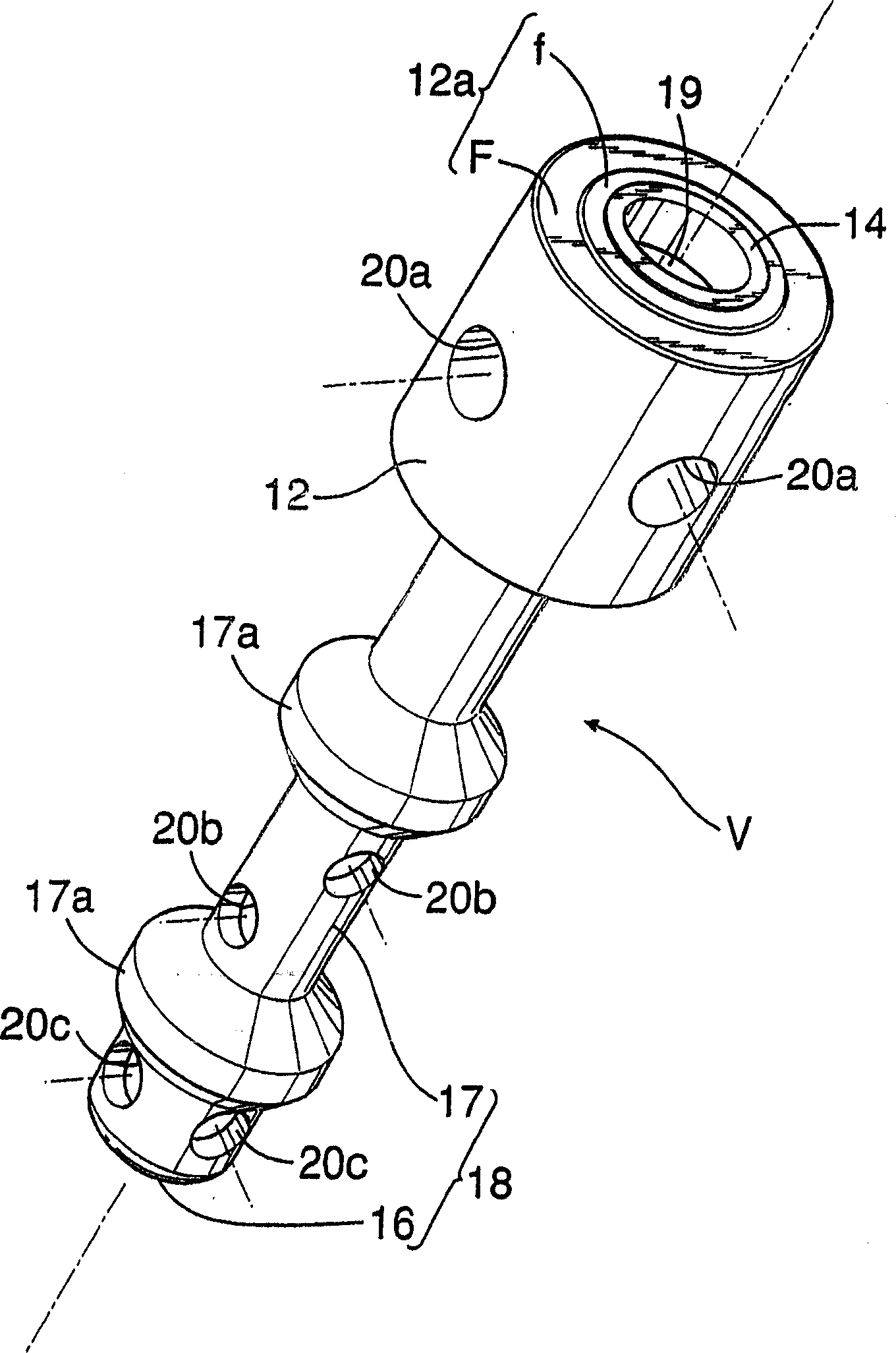
[0042] First, from Figure 1 to image 3 The description will begin with the first embodiment of the present invention shown.

[0043] In Fig. 1, the valve housing 2 of the electromagnetic fuel injection valve 1 for an internal combustion engine has: a cylindrical valve seat member 3 with a valve seat 8 at the front end; a cylinder 4 ; and a non-magnetic cylinder 6 coaxially coupled to the rear end of the magnetic cylinder 4 .

[0044] The valve seat member 3 has a connection cylinder portion 3 a at the rear end thereof, and the connection cylinder portion 3 a protrudes from an annular shoulder 3 b on the outer periphery of the valve seat member 3 toward the magnetic cylinder 4 . The valve s...


PUM


Abstract

In an electromagnetic type fuel injection valve (1), a fixed core (5) is made of ferritic high-hardness magnetic material, while a movable core (12) has fixed therein by a press fit a stop element (14) which comes in direct contact with the fixed core (5) during excitation of a coil (30) with an air gap (g) held between the two cores (5, 12) and which is non-magnetic or less magnetic than the movable core (12). Thus, the two cores can be given high wear resistance and responsiveness without applying a troublesome wear resistance treatment, such as plating, to the fixed and movable cores or without installing a stop plate for the valve body, a fact which can contribute to cost reduction of electromagnetic type fuel injection valves.

Description

technical field [0001] The present invention mainly relates to an electromagnetic fuel injection valve used in an internal combustion engine supply system, in particular to an improved electromagnetic fuel injection valve, which has: a valve housing with a valve seat at one end; connected to the other end of the valve housing a fixed magnetic core; a valve body accommodated in the valve housing and cooperating with the valve seat for switching action; a movable magnetic core integrally connected with the valve body and facing the fixed magnetic core; a valve spring that imparts potential energy to the valve body in a valve closing direction; and a coil that is disposed around the fixed magnetic core and attracts the movable magnetic core to the fixed magnetic core by excitation to open the valve body. Background technique [0002] In the existing electromagnetic fuel injection valve, the movable magnetic core is directly attracted to the fixed magnetic core through the excit...

Claims


Application Information

Patent Timeline
Patent Type & Authority Patents(China)
IPC IPC(8): F02M51/06
Inventor 赤羽根明
Owner HITACHI ASTEMO LTD
Learn More