Electronic pipette

a technology of electronic pipette and magnetic disc, which is applied in the field of electronic pipette, can solve the problems of inability to ensure inability to determine the passing through of different poles sufficiently reliably through magnetic sensors, and inability to achieve trouble-free operation of the pipette over a long period of use. achieve the effect of increasing the positioning accuracy of the magnetic disc, increasing the magnetic interaction, and strong magnetic interaction

Active Publication Date: 2009-09-08
EPPENDORF SE
View PDF21 Cites 14 Cited by
  • Summary
  • Abstract
  • Description
  • Claims
  • Application Information

AI Technical Summary

Benefits of technology

[0018]The electronic pipette namely does not allow the volume of fluid to be metered to be adjusted at will. However, it does allow the highly precise adjustment of discrete fluid volumes, where the magnetic disc is held in a precisely defined position by the additional magnet. The resolution of the setting of the fluid volume to be metered depends in particular on the transmission ratio of the gear mechanism and the number of magnetic poles on the magnetic disc. Preferably, the resolution of the setting of the volume of fluid to be metered is adjusted to the resolution of a display device for the adjusted volume of fluid (for example, a digital display) and / or to the resolution of an input device (for example a keypad) to adjust the volume of fluid to be metered. Then each displayable or adjustable volume of fluid can be metered by means of the electronic pipette. The adjustable volumes of fluid are always very precisely adhered to, due to the adjustment of the magnetic disc effected by the additional magnet into a defined angular position at the end of the adjustment of the magnetic disc by the drive motor.
[0033]When the electric drive motor is switched on at the end of the positioning of the magnetic disc, a positioning error results due to the load torque which is however substantially less than with conventional electronic pipettes with magnetic discs without additional magnets. According to an embodiment, the electronic control device switches off the electronic drive motor when it establishes, due to the signals emitted by the at least one magnetic sensor, that the magnetic disc has approached a predetermined position. By switching off the drive motor, the load torque decreases and the precise positioning is facilitated due to the magnetic interaction between the at least one additional magnet and the magnetic disc. Switching off the drive motor can result when the control device, due to a comparison of the signals with a limit value emitted by at least one sensor, detects that a magnetic pole to be aligned with the additional magnet has approached the additional magnet at a distance which is smaller than half the distance between two adjacent magnetic poles on the magnetic disc. Then it is ensured that the magnetic pole to be aligned, is aligned with the additional magnet after switching off the drive motor.

Problems solved by technology

The mechanical braking of the piston by means of the brake is prone to wear and tear.
As a result, trouble-free operation of the pipette over a lengthy period of use is not guaranteed.
Furthermore, the passing through of different poles can only be determined sufficiently reliably by means of the magnetic sensor.
However, the exact position of the magnetic disc cannot be measured by the sensor in the space between the poles.
Moreover, oscillation controllers are possible with the rotational movements of the magnetic disc, which are limited by the spacing between the different poles.
The electronic processing of the signals emitted by the Hall-effect sensors to establish precisely the rotational position of the magnetic sender disc is costly.

Method used


Image

  • Electronic pipette
  • Electronic pipette

Examples


Embodiment Construction

[0038]While this invention may be embodied in many different forms, there are described in detail herein a specific preferred embodiment of the invention. This description is an exemplification of the principles of the invention and is not intended to limit the invention to the particular embodiment illustrated

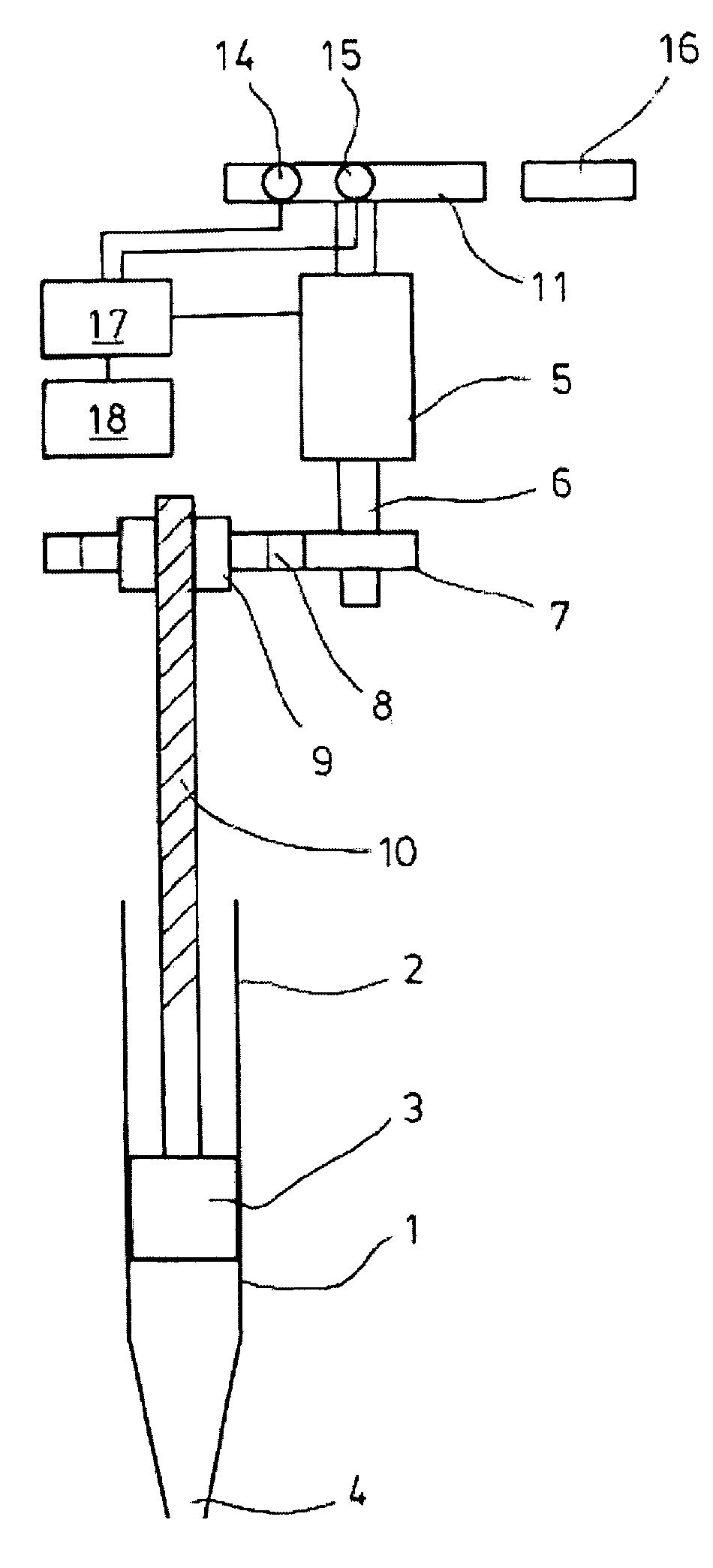
[0039]According to FIG. 1 an electronic pipette has a displacement device 1, which comprises a cylinder 2 with a piston 3 longitudinally displaceable therein. Releaseably (air cushion pipette) or individually (direct displacement pipette) attached to the cylinder 2 is a tip 4 which is a pipette tip or a syringe tip.

[0040]Moreover, the pipette comprises an electric drive motor 5, which comprises a drive shaft 6. The drive motor is a DC motor.

[0041]On a portion of the drive shaft 6 a small pinion 7 is positioned which meshes with a large pinion 8 which is rotationally fixedly attached to a spindle nut 9.

[0042]The spindle nut 9 is screwed onto a threaded spindle 10. The threaded ...


PUM


Abstract

Electronic pipette with a displacement device, an electric drive motor with a drive shaft, a gear mechanism coupled on the one hand to the displacement device and on the other hand to the drive shaft, a magnetic disc rotationally coupled to the drive shaft with at least one magnetic pole on the circumference, at least one magnetic sensor aligned with the circumference of the magnetic disc, at least one additional magnet aligned with the circumference of the magnetic disc, an electronic control device electrically connected to the electric drive motor and the magnetic sensor and an electric voltage supply connected to the electronic control device.

Description

CROSS-REFERENCE TO RELATED APPLICATIONS[0001]Not applicable.STATEMENT REGARDING FEDERALLY SPONSORED RESEARCH[0002]Not applicable.BACKGROUND OF THE INVENTION[0003]Electronic pipettes are used in the laboratory for metering fluids. They are known in different embodiments. Air cushion pipettes have an integral cylinder with a piston arranged therein. The cylinder is attached to an aperture in a fastening shoulder via a channel. A pipette tip can be releasably connected to the fastening shoulder. By displacing the piston in the cylinder, test fluid is drawn into the pipette tip or ejected therefrom. In this connection, the piston and cylinder do not come into contact with the fluid, as the piston moves the fluid indirectly via the air cushion. Only the pipette tip, which generally consists of plastics, is contaminated and can be exchanged after use.[0004]Direct-displacement pipettes can be releasably connected to a syringe, of which the piston can be driven by means of the pipette in or...

Claims


Application Information

Patent Timeline
Patent Type & Authority Patents(United States)
IPC IPC(8): B01L3/02
CPCB01L3/0224B01L3/0227B01L2200/143
Inventor JAGHUBER, BERND
Owner EPPENDORF SE
Why Eureka
Try Eureka