
Automatic Bow Sighting Device with Range Finding Means

Inactive Publication Date: 2011-12-08
MAINSONNEUVE BENOIT +1
View PDF6 Cites 17 Cited by
  • Summary
  • Abstract
  • Description
  • Claims
  • Application Information

AI Technical Summary

Benefits of technology

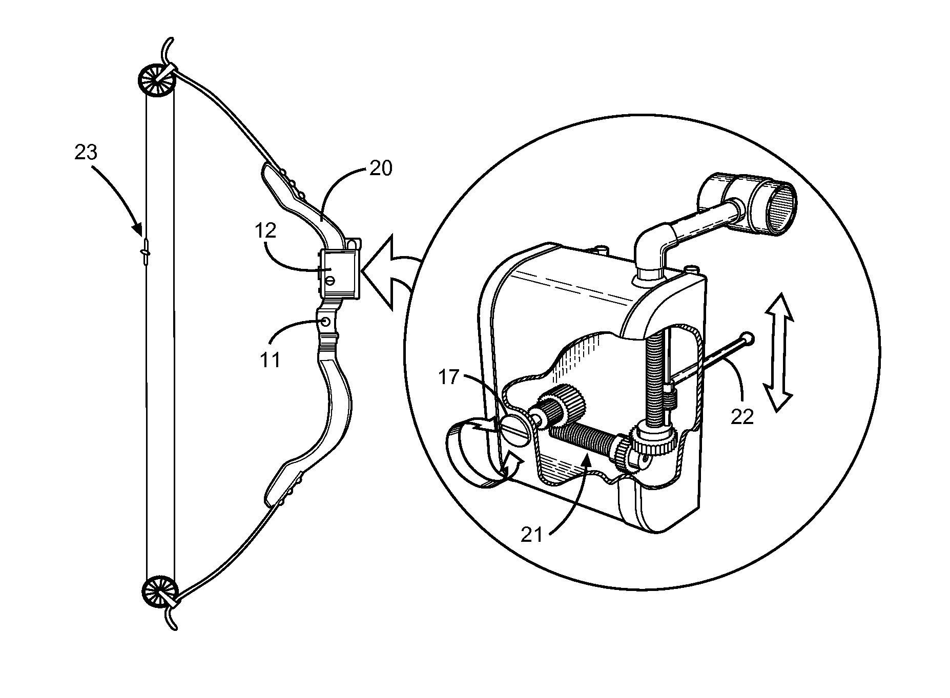
[0016]The present invention fulfills a need in the art by providing a compact sighting device that includes a range finding means, an electronic controller, and a gearing mechanism for automatically updating the vertical position of a sighting pin given a designated target distance. The elevation of the sighting pin allows the user to adjust the trajectory of the arrow by adding inclination to the initial arrow release vector. The range finding means determines the distance to a target and the onboard microprocessor interpolates between calibrated preset distances for a given bow. Internal circuit logic and programming of a microprocessor automates the sightin pin vertical position by based on the range finder input and comparing with historically stored data relating to the present bow. The initial velocity of the arrow and the drop over a given distance is compared to the measured distance to ensure the sighting pin is aligned in such a manner as to allow the arrow to impact a desired target, particularly at long ranges.
[0018]The present invention serves several functions, namely to provide an automatic means of sighting adjustment and to improve the accuracy of long-distance archery shots. This is particularly useful for hunters, as wounded animals may not be harvested, and misguided arrows may squander a precious opportunity.
[0020]Another object of the present invention is to remove errors associated range estimation and preset distance memorization while aiming at a target and preparing to release an arrow.
[0021]Yet another object of the present invention is to provide a sighting device that determines the range to target after a user has retracted the bow and designated a target by aligning a peep sight with the range finder reticle, providing accurate measurements from a firing position.

Problems solved by technology

This is particularly useful for hunters, as wounded animals may not be harvested, and misguided arrows may squander a precious opportunity.

Method used


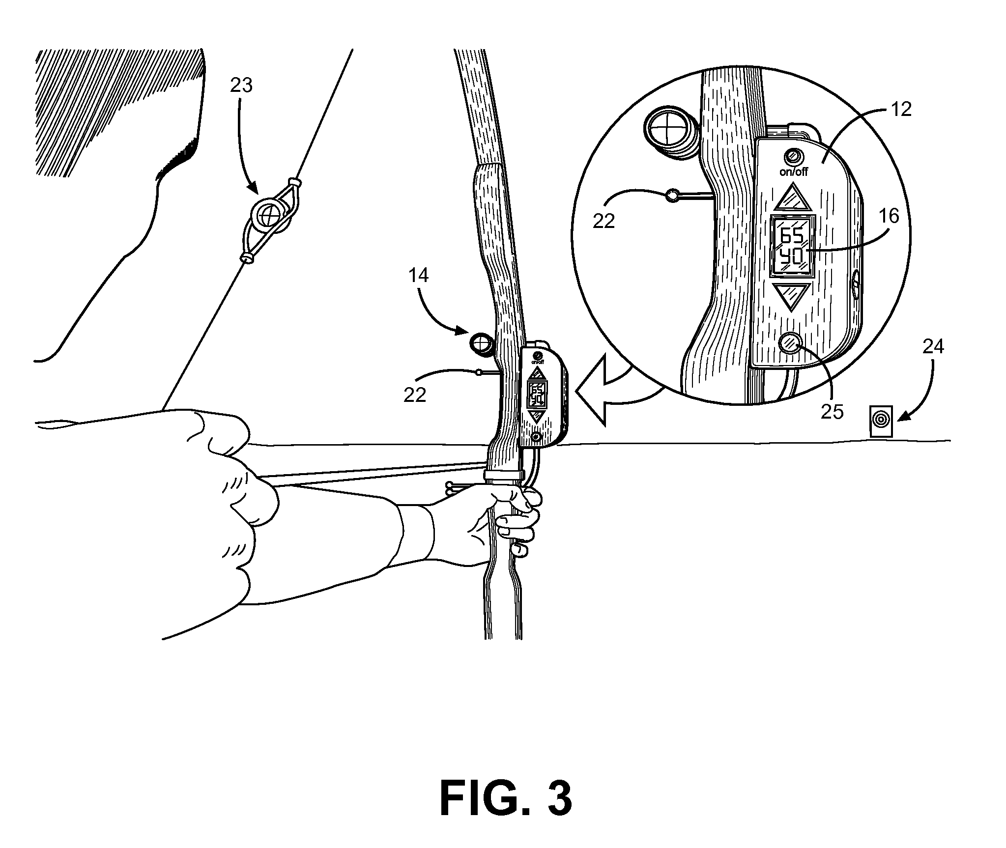
Image

  • Automatic Bow Sighting Device with Range Finding Means
  • Automatic Bow Sighting Device with Range Finding Means
  • Automatic Bow Sighting Device with Range Finding Means

Examples


Embodiment Construction

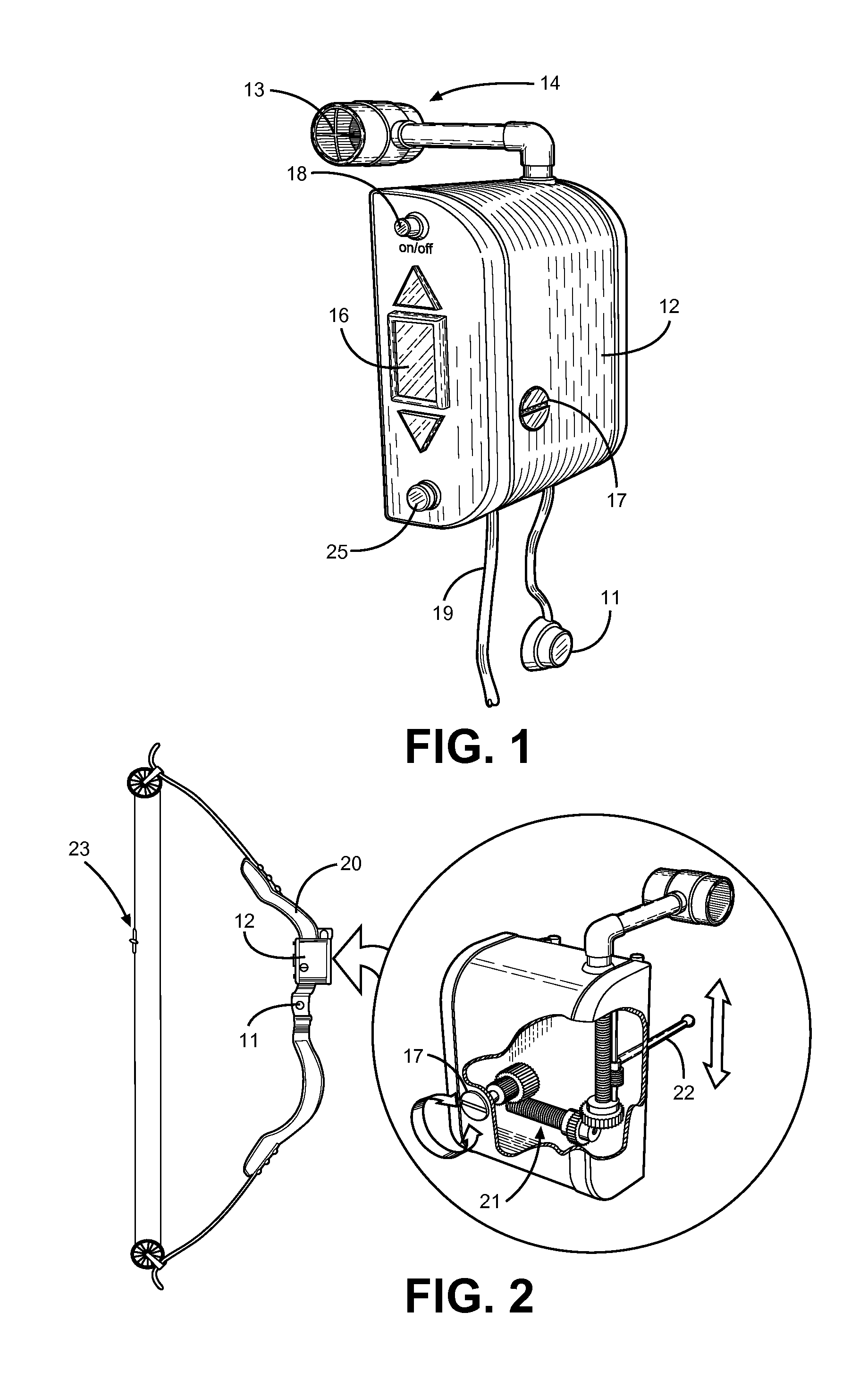
[0027]Referring now to FIG. 1, there is shown a rear perspective view of the present invention. The device comprises sighting device housing 12, which provides enclosure for imbedded electronics and mechanical gearing, along with support for external accessories and attachments to an archery bow. Along the backside of the housing 12 is a user-facing display 16, a power button 18 and fire-ready indicator light 25. The display is a digital interface for the user to reference a target distance, measured by an imbedded laser range finding means. The display provides a read-out for the user, noting a numerical distance in yards for which the sighting pin elevation is positioned. This provides the user with a quick reference with regard to the measured distance, without reliance on memory or requiring the user to alter his or her vision while retracting the bow.

[0028]Above and below the display 17 are and up arrow and down arrow buttons. These buttons allow the user to program the preset ...


PUM


Abstract

Disclosed is an archery bow sighting device that incorporates a laser range finder, an automatically adjusting sight pin, trigger control and distance indicator. The device incorporates imbedded electronics and a gearing mechanism to adjust a sighting pin based on distance to target and calibrated distance data. The user aims the laser range finder at a designated target for determination of its distance, after which the sight pin is automatically adjusted to account for the distance and is used to aim at the target. To accurately aim the range finder, a peep sight along the length of the bow string is aligned with crosshairs within the range finder while aiming at the intended target. A trigger button along the bow pulses the laser range finder to determine distance, and the sighting pin elevation is updated accordingly by the imbedded electronic circuit and interpolation of preset distances. The device is attachable to any archery bow sight rail, and provides a means to quickly update a range to target if the target is mobile. A trigger button controls the device in use, while power is supplied by a user harnessed battery pack and wire tether.

Description

CROSS REFERENCE TO RELATED APPLICATION[0001]This application claims the benefit of U.S. Provisional Application No. 61 / 350,946 filed on Jun. 3, 2010, entitled “Automatic Sighter.”BACKGROUND OF THE INVENTION[0002]1. Field of the Invention[0003]The present invention relates to archery bow sighting devices. More specifically, the present invention pertains to an automatically adjusting archery sight device that responds to input from an imbedded laser range finding device for tracking mobile and long-distance targets. A singular sighting pin is provided along a motorized track. Input from the laser range finder updates the sighting pin elevation along its track and notifies the user of the target distance through a backward facing digital display. Input from the laser range finder and corresponding output to the sighting pin is controlled by an internal electronic circuit, which interpolates between preset distances determined when calibrating a given archery bow. Power for the device ...

Claims


Application Information

Patent Timeline
IPC IPC(8): F41G1/467
CPCF41G1/467
Inventor MAINSONNEUVE, BENOITCOURVILLE, JACQUES
Owner MAINSONNEUVE BENOIT
Learn More