Method for calibrating a medical imaging device, method for performing a 2d-3d registration, and system including a medical imaging device

Active Publication Date: 2019-06-27
SIEMENS HEALTHCARE GMBH
View PDF2 Cites 3 Cited by
  • Summary
  • Abstract
  • Description
  • Claims
  • Application Information

AI Technical Summary

Benefits of technology

[0025]In any case, the ruler device may include one or more sensors for detecting when and where the protrusion of the phantom enters one of the notches or recesses of the ruler device. The ruler device may then provide corresponding data, for example, to a control unit configured to calibrate the imaging device. This may remove any human error in reading the current position of the phantom. Depending on an effort and a precision put into manufacturing the ruler device and the phantom, this approach may enable determining the respective current position of the phantom with a precision on the order of 0.1 mm or less.
[0026]In a development, to track the motion of the phantom, the phantom is moved by a linear stage. A linear stage enables precisely controlled motion along one axis and is also known as a translation stage or linear slide. Typical applications for a linear stage may, for example, be found in optics lab stages. Applied to the presently described method, the linear stage may, for example, be placed upon or mounted to a patient support. The phantom may be placed on top of the linear stage and thus may be moved as a payload of the linear stage. Non-moving parts of the linear stage may remain stationary with respect to the room coordinate system and/or with respect to the patient support on which the non-moving parts of the linear stage may be placed. Operating the linear stage to move the phantom may be done manually. In one embodiment, however, the linear stage may be motorized and, for example, electronically controlled (e.g., by the control unit). A linear stage provides a simple to implement or apply, precise, and relatively inexpensive way for moving the phantom in a precise, trackable, and controllable manner to extend the size of the calibration space (e.g., a number of and volume covered by calibrated imaging positions). Linear stages are available with travels of, for example, about 400 mm, which may be enough to significantly increase the calibration space as compared to conventional methods where the phantom remains stationary.
[0027]In a development, as at least part of the tracking device, a laser dist

Problems solved by technology

These same imaging techniques may, however, also expose the patient to significant radiation.
A precise registration with reasonable effort is typically only possible for imaging positions for which the imaging device has previously been calibrated.

Method used


Image

  • Method for calibrating a medical imaging device, method for performing a 2d-3d registration, and system including a medical imaging device
  • Method for calibrating a medical imaging device, method for performing a 2d-3d registration, and system including a medical imaging device

Examples


Example

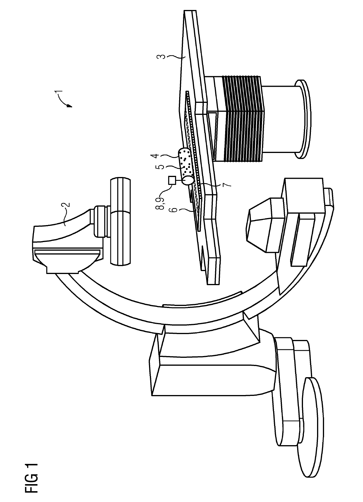
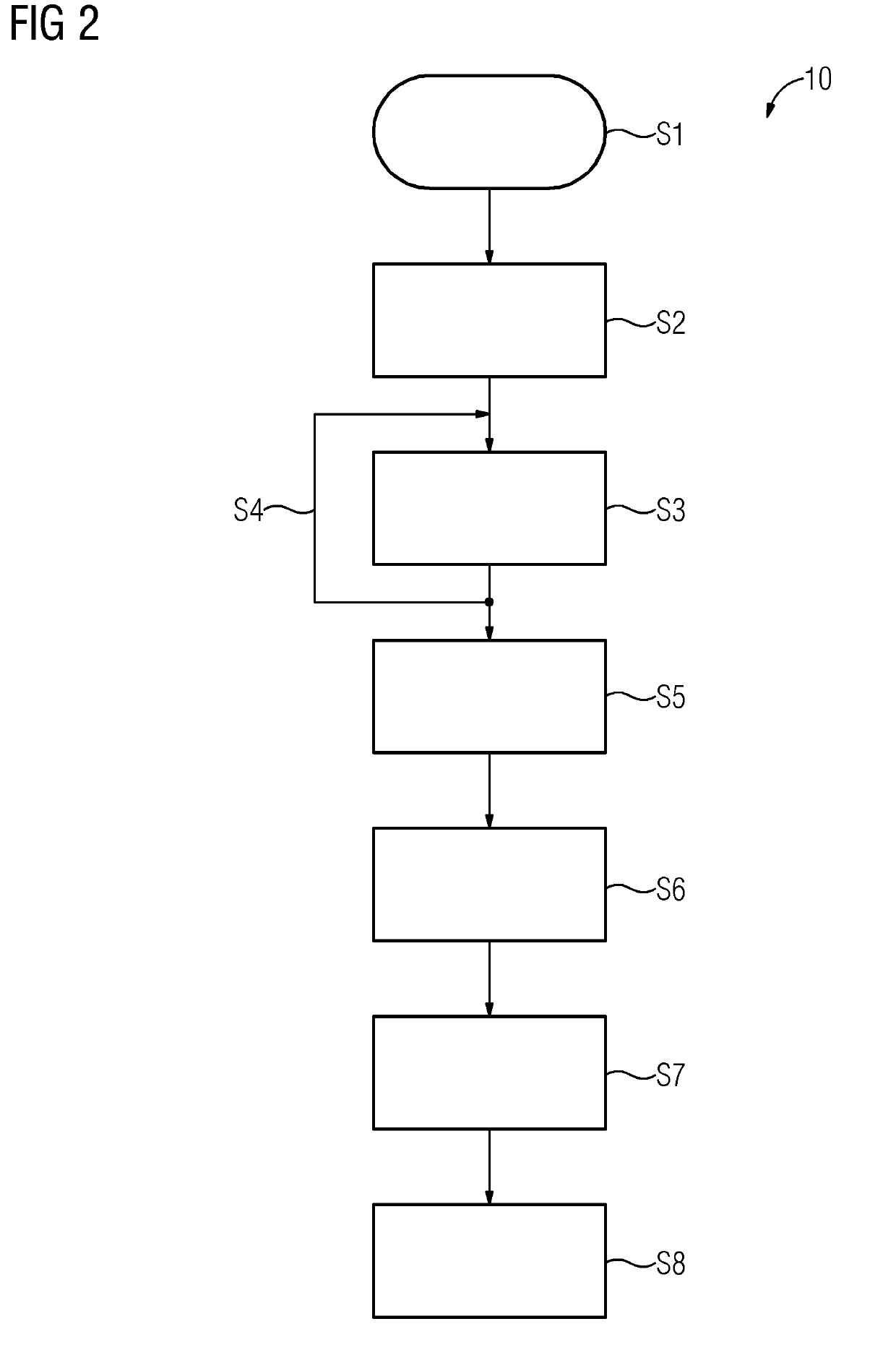
[0038]FIG. 1 schematically shows one embodiment of a system 1 including a medical imaging device 2 that, in the present example, is a c-arm x-ray device. The system 1 or the imaging device 2, respectively, further includes a patient support 3 that is adjustable. Placed on the patient support 2 is an imaging phantom 4 in the form of a cylindrical object including multiple x-ray-visible markers 5 arranged in a pattern to uniquely or unambiguously identify a pose of the phantom 4 in or from x-ray images or corresponding image data obtained using the imaging device 2. Because a geometry of the phantom 4 and the pattern of markers 5 is predetermined and known, the phantom 4 may be used to calibrate the imaging device 2. A corresponding method for calibrating the imaging device 2 will be described with reference to FIG. 2, which schematically shows an exemplary flow chart 10, illustrating multiple process acts.

[0039]The method starts with a process act S1, where the phantom 4 is positione...


PUM


Abstract

A method for calibrating a medical imaging device in terms of an image acquisition geometry, a method for performing a two-dimensional-three-dimensional registration based on corresponding calibration data, and a corresponding system are provided. Multiple images of a phantom are acquired using the imaging device in different positions of the phantom. A corresponding motion of the phantom from one position to a respective next position is tracked by a tracking device to keep continuous track of a spatial relation between the phantom and the imaging device. The medical imaging device is then calibrated based on the acquired images, corresponding recorded poses of the imaging device, and the tracked motion of the phantom.

Description

[0001]This application claims the benefit of EP 17210234.5, filed on Dec. 22, 2017, which is hereby incorporated by reference in its entirety.BACKGROUND[0002]The present embodiments relate to calibrating a medical imaging device and performing a two-dimensional (2D)-three-dimensional (3D) registration.[0003]Today, medical imaging techniques, such as computer tomography (CT), x-ray imaging, angiography, and others may provide detailed image data of a patient and may thereby contribute to a successful diagnosis and treatment of a patient. These same imaging techniques may, however, also expose the patient to significant radiation. It is therefore common practice to acquire a full 3D dataset of the patient or a region of interest (ROI) only once, typically before actual intervention or operation. During the intervention or operation, only 2D images of the patient or ROI are then acquired instead of multiple full 3D datasets to reduce exposure or stress of the patient. This approach doe...

Claims


Application Information

Patent Timeline
IPC IPC(8): A61B6/00A61B90/00A61B6/03
CPCA61B6/584A61B90/37A61B6/032A61B6/547A61B6/488A61B6/4441A61B2090/367A61B6/469A61B2090/3762A61B6/504A61B6/582A61B6/542A61B6/487A61B6/5235A61B6/583A61B6/0487
Inventor MEWES, PHILIPMULLER, GUNTERFISCHER, PETERMONNICH, HOLGERRUBE, MARTIN
Owner SIEMENS HEALTHCARE GMBH
Why Eureka
Try Eureka