
Vacuum lock transitional cavity

A technology of vacuum lock and transition cavity, which is applied in the field of microelectronics, can solve the problems of poor control of the cleanliness of the vacuum lock chamber, low output rate, and impact on output rate, etc., to achieve good adjustability and good cleanliness , the effect of increasing the output rate

Active Publication Date: 2008-05-14
BEIJING NAURA MICROELECTRONICS EQUIP CO LTD
View PDF4 Cites 0 Cited by
  • Summary
  • Abstract
  • Description
  • Claims
  • Application Information

AI Technical Summary

Problems solved by technology

The disadvantage is that the volume of the chamber is large, and the time for filling and pumping is long, which affects the output rate of the entire transmission system.
In addition, due to the lifting action, the ability to control the cleanliness of the vacuum lock chamber is poor
The vacuum lock transition chamber carrying two pieces, although the volume of the chamber is small, but because the number of wafers exchanged each time is small, the number of exchanges is more, which affects the output rate from another aspect.
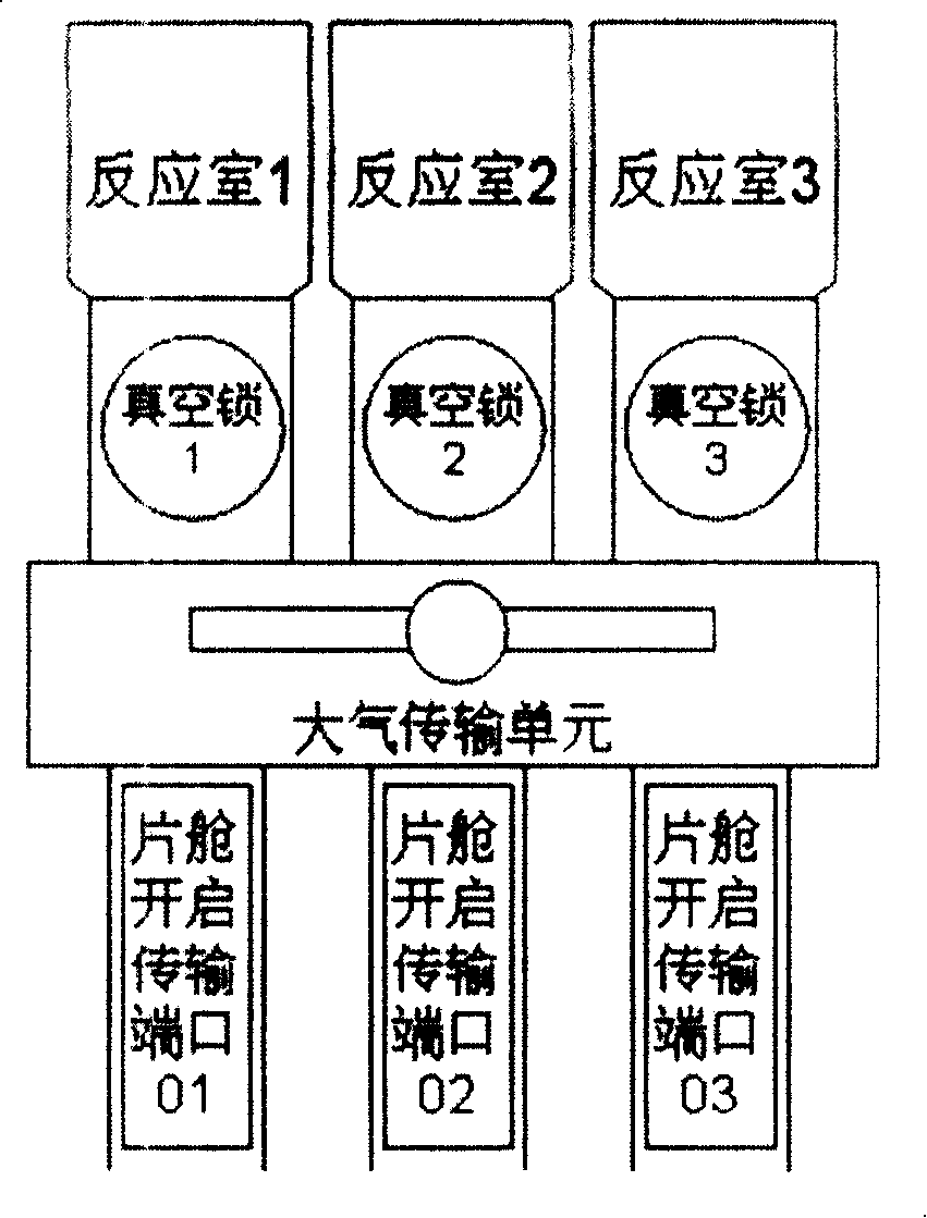
[0005] like image 3 As shown, the vacuum lock transition chamber in the 300mm platform method 2: there is no vacuum transfer chamber, and the wafer is directly transferred to the reaction chamber through the vacuum manipulator installed in the vacuum lock. The disadvantage is that the chamber volume is large, and each time The number of exchange chips is 1-2, so there is still a phenomenon that the output rate is not high

Method used


Image

  • Vacuum lock transitional cavity
  • Vacuum lock transitional cavity
  • Vacuum lock transitional cavity

Examples


Embodiment Construction

[0022] The following examples are used to illustrate the present invention, but are not intended to limit the scope of the present invention.

[0023] Such as Figure 5 Shown, when the present invention is carried out, comprise chamber 5, the inflation system 1 on the chamber and the air extraction system 2, the valve A, B of chamber end, also be provided with wafer supporting device 7, in described chamber 5, The base 6, wherein the bottom of the supporting device 7 is connected to the base 6.

[0024] Such as Figure 5 As shown, the present invention adopts a four-layer wafer supporting device 7, which can exchange 4 wafers during one filling and pumping process of the vacuum lock transition chamber. According to the SEMI standard (semiconductor industry standard), the height of the 300mm wafer transmission opening is 50mm, and the spacing between each layer of wafers is also stipulated as 10mm. In this way, in the vacuum lock transition chamber, four layers of wafers can...


PUM


Abstract

The disclosed transition chamber of vacuum lock includes chamber, gas pressure system and gas-extraction system on upper part of the chamber, and valve at end part of the chamber. Wafer support device and base are also setup inside the chamber. The bottom part of the support device is connected to the base. Comparing with prior art, the invention increases rate of output of transmission system greatly, guarantees good adjustability, flexibility, and compatibility of transition chamber of vacuum lock for different sizes of wafers, different loading height, and structures of front end of different mechanical hands. Advantages are: simple structure, and good control for degree of cleanliness inside transition chamber of vacuum lock.

Description

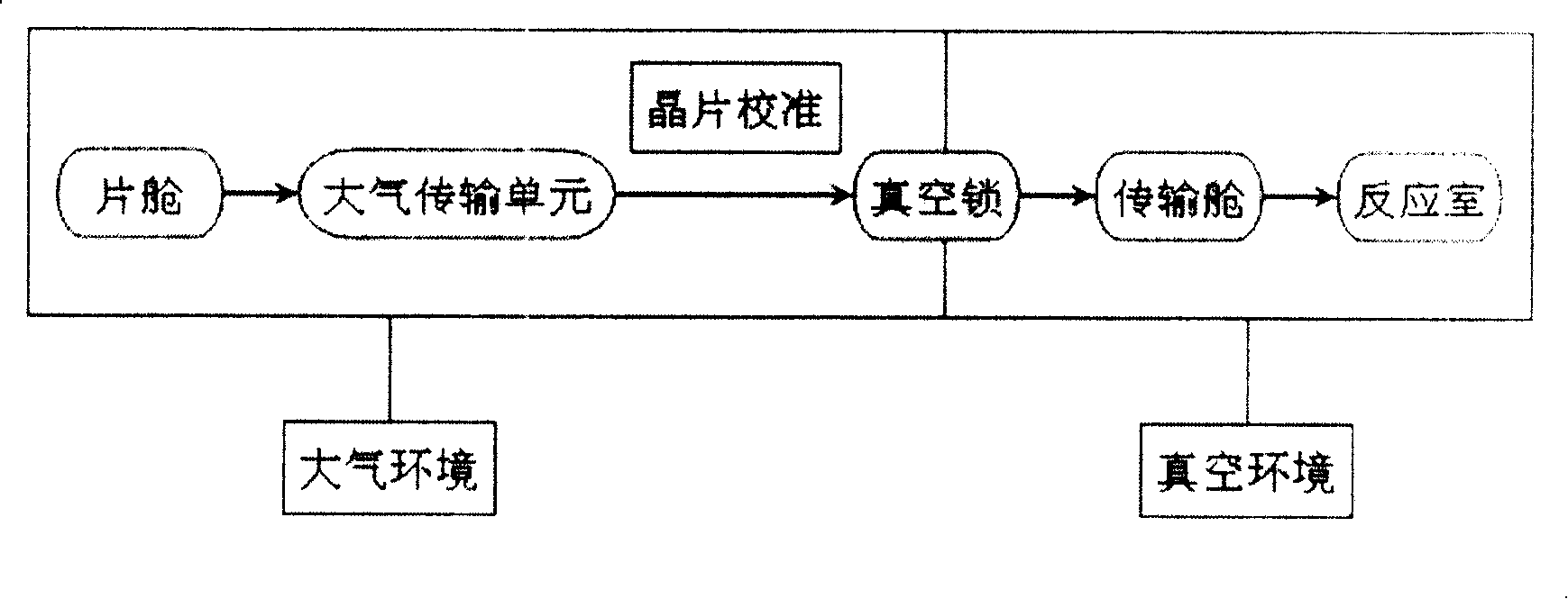
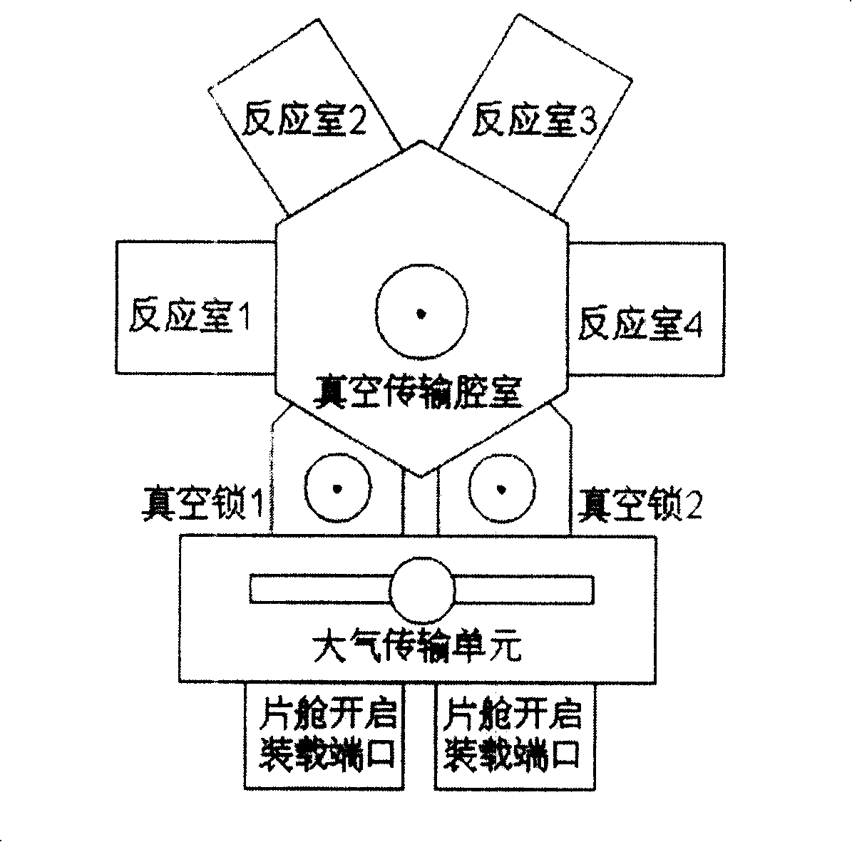
technical field [0001] The invention relates to the technical field of microelectronics, in particular to a vacuum lock transition chamber for the transmission and processing of semiconductor wafers. Background technique [0002] Such as figure 1 As shown, in the transmission and processing of semiconductor wafers, the wafer is processed from the wafer chamber to the reaction chamber, and after the process is completed, the wafer is transferred back from the reaction chamber to the wafer chamber. The vacuum lock transition chamber is an important step in the wafer transfer process. Such as figure 2 , image 3 As shown, there are two structures adopted by most semiconductor 300mm platforms at present. [0003] Such as Figure 4 As shown, when the atmospheric manipulator holds the wafer to be processed and is ready to transfer to the reaction chamber, valves A and B are closed, and the vacuum lock transition chamber is inflated to atmospheric pressure; A is opened, and t...

Claims


Application Information

Patent Timeline
Patent Type & Authority Patents(China)
IPC IPC(8): H01L21/677
Inventor 张之山
Owner BEIJING NAURA MICROELECTRONICS EQUIP CO LTD
Learn More