

Container having sealing strip at floor splicing seam
A technology of sealing strips and splicing seams, applied in the field of containers, can solve problems such as weakening of floor strength, and achieve the effects of improving strength, simple sealing method and improving service life
- Summary
- Abstract
- Description
- Claims
- Application Information
AI Technical Summary
Problems solved by technology
Method used
Image

Examples
Embodiment Construction
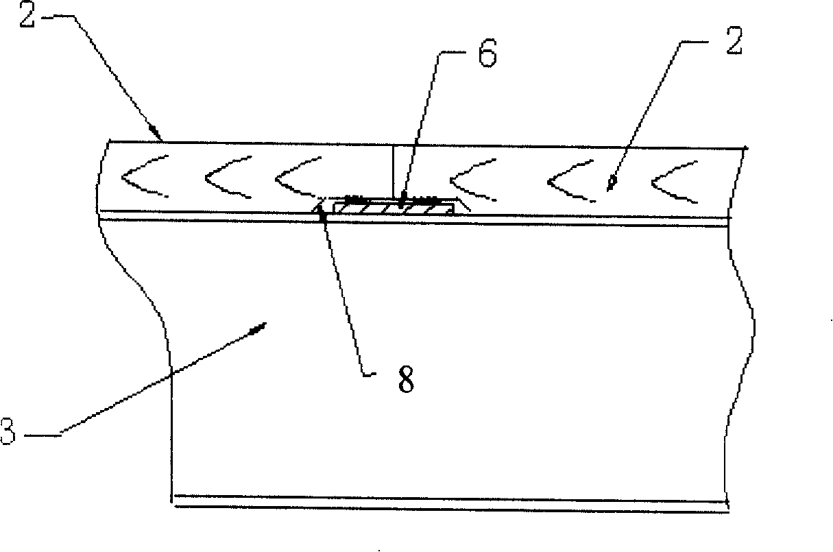
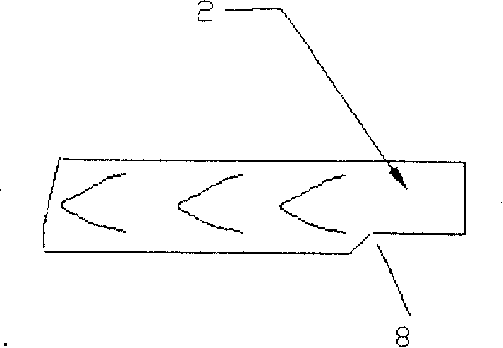
[0019] A preferred embodiment of the present invention is Figure 4 with Figure 5 As shown, at each longitudinal seam, a first inclined notch is provided at the end of the left floor 2, and a second inclined notch is provided at the end of the right floor 2. The first and second inclined notches Cooperate with each other to form a downward sealing strip installation groove 7 with a triangular cross-section; in the sealing strip installation groove, a triangular-shaped sealing strip 51 is installed. When assembling, it is necessary to apply glue on the surface of the sealing strip first, and then squeeze the sealing strip to attach to the sealing strip installation groove of the floor to form a good seal.
[0020] exist Image 6 In the shown embodiment 2, the inclined gaps on the left and right floors also form a sealing strip installation groove with a triangular cross-section and opening downwards, but the depth of the sealing strip installation groove is smaller than the ...
PUM
 Abstract
Description
Claims
Application Information