
Valve set structure for reciprocating compressor

A compressor and reciprocating technology, applied in the direction of liquid variable capacity machinery, mechanical equipment, variable capacity pump components, etc., can solve the problems of reduced reliability of the valve plate, too soft, valve plate vibration, etc., to reach the valve port Grinding quality assurance, easy manufacturing, and the effect of reducing exhaust loss

Active Publication Date: 2008-06-04
JIAXIPERA COMPRESSOR
View PDF4 Cites 0 Cited by
  • Summary
  • Abstract
  • Description
  • Claims
  • Application Information

AI Technical Summary

Problems solved by technology

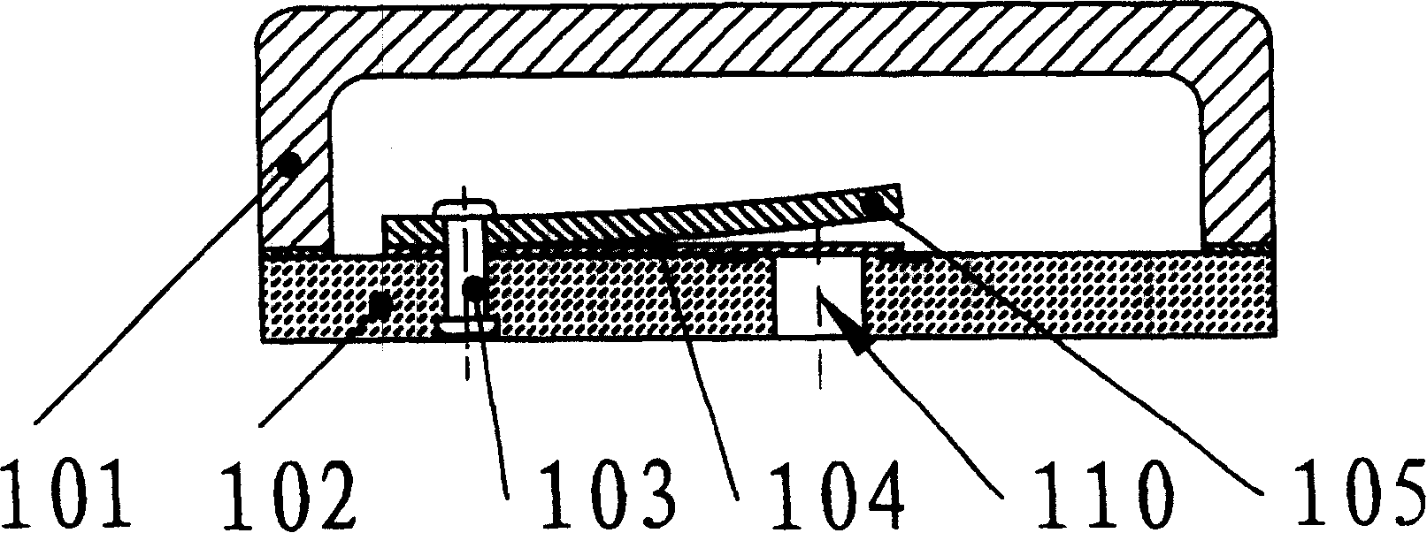
However, if it is too soft, it may cause the vibration of the valve plate when it is working. At the same time, the opening height of the valve plate may be too large, and the reliability of the valve plate will also be reduced.

Method used


Image

  • Valve set structure for reciprocating compressor
  • Valve set structure for reciprocating compressor
  • Valve set structure for reciprocating compressor

Examples


Embodiment Construction

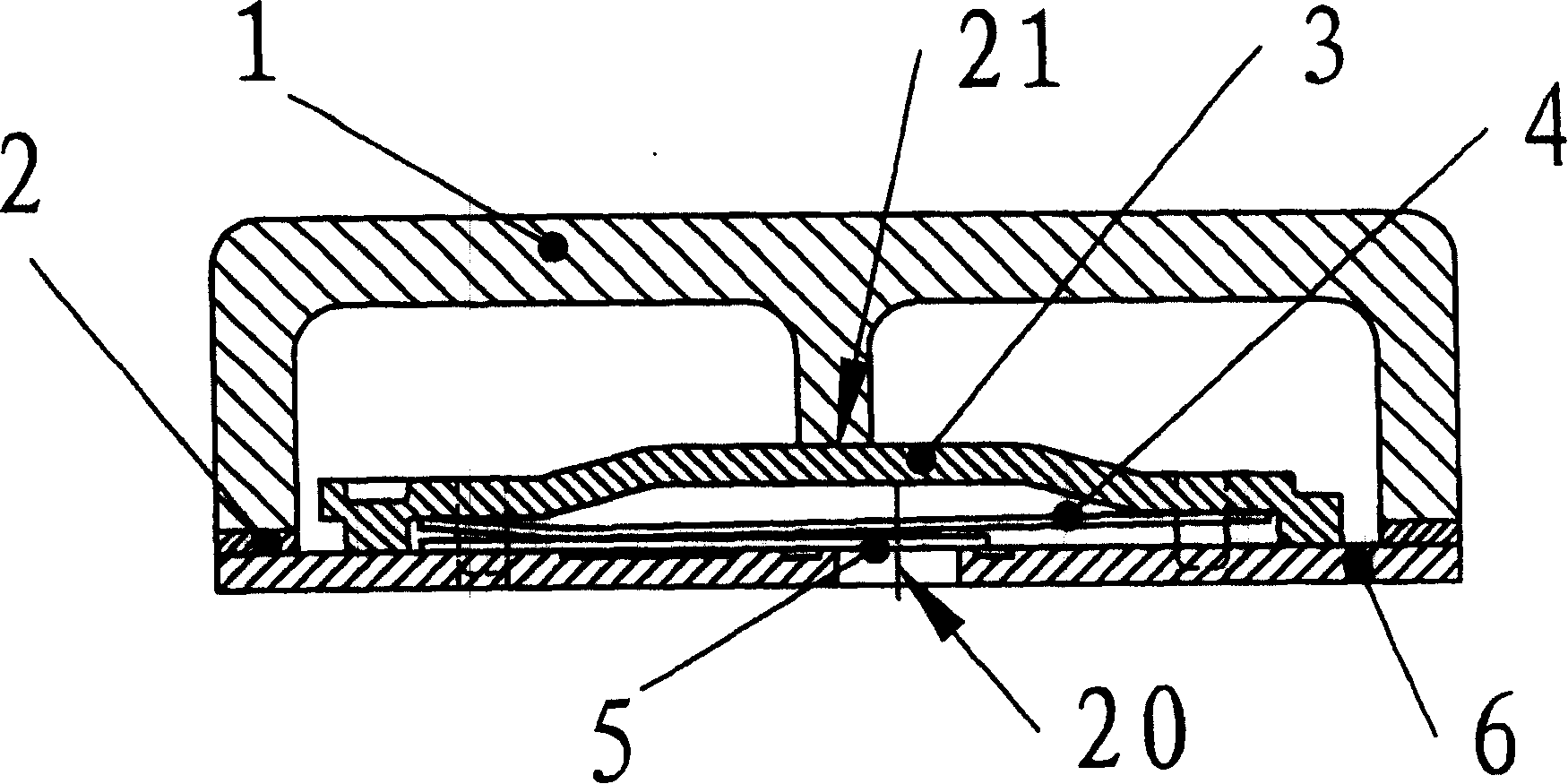
[0018] Such as image 3 As shown, the valve block structure of the reciprocating compressor of the present invention consists of a cylinder head 1, a cylinder head gasket 2, a valve plate support 3, an elastic plate 4, an exhaust valve plate 5 and a thin steel valve plate 6. Since the flat valve plate is still used, the grinding process of the suction and exhaust valve ports can be guaranteed to achieve a high airtight pass rate. At the same time, the valve plate of the present invention is stamped from steel material, and the thickness can reach 1.5 mm or less, so that the compressor can achieve the same clearance volume as the concave valve plate structure or less. Compared with the traditional valve plate, the valve plate 6 of the present invention only adds four mounting holes for valve plate brackets on the valve plate 6, without increasing any process difficulty. When installing the exhaust valve group, the exhaust valve plate 5, the elastic plate 4 and the valve plate ...


PUM


Abstract

The invention discloses reciprocating compressor valve block structure. It includes steeliness valve plate, exhaust valve plate, valve plate support, air suction valve plate, valve plate spacercy, cylinder cover, cylinder cover spacercy and elastic plate. The valve plate is plane. The exhaust valve plate and elastic valve plate are fixed on the valve plate. It has the advantages of good technology assurance and low air tight seal underline rate. This can improve clearance volume efficiency and compressor working efficiency.

Description

technical field [0001] The invention relates to a valve group structure for a reciprocating compressor, especially a reciprocating refrigerator refrigeration compressor. technical background [0002] A reciprocating refrigerator compressor generally includes a valve group, a cylinder, a piston, a connecting rod, a crankshaft, and an electric motor that drives them. The pump body composed of them is placed in a closed casing. Through the operation of the motor, the crankshaft and connecting rod mechanism is driven to push the piston to reciprocate. The suction valve and exhaust valve in the valve group are intermittently opened and closed under the action of the piston, and the refrigerant is continuously sucked and discharged, thus forming an intermittent cycle. refrigerant flow. At the end of each compression process of the piston, the residual volume formed between the end of the piston and the valve plate is called the clearance volume. The clearance volume has a very im...

Claims


Application Information

Patent Timeline
Patent Type & Authority Patents(China)
IPC IPC(8): F04B39/10
Inventor 陆海江姚辉军张韦林严志奇
Owner JIAXIPERA COMPRESSOR
Learn More