
Visible laser detector

The technology of a laser detector and a laser transmitter is applied in the field of obstacle detectors on vehicles, which can solve the problems of poor light penetration, small illumination range of car lights, and inability of drivers to better distinguish road conditions. Achieve the effect of low cost, small size and simple structure

Inactive Publication Date: 2008-06-04
WUHAN UNIV OF TECH
View PDF10 Cites 0 Cited by
  • Summary
  • Abstract
  • Description
  • Claims
  • Application Information

AI Technical Summary

Problems solved by technology

[0003] Although the headlight system of modern vehicles has made great progress and the products are diverse, it still cannot meet the requirements of drivers. The main manifestations are: 1. There is a small range of light irradiation; In the case of interference such as rain, fog or smoke, the driver cannot better distinguish the road conditions; these are also important factors affecting the occurrence of traffic accidents

Method used


Image

  • Visible laser detector

Examples


Embodiment Construction

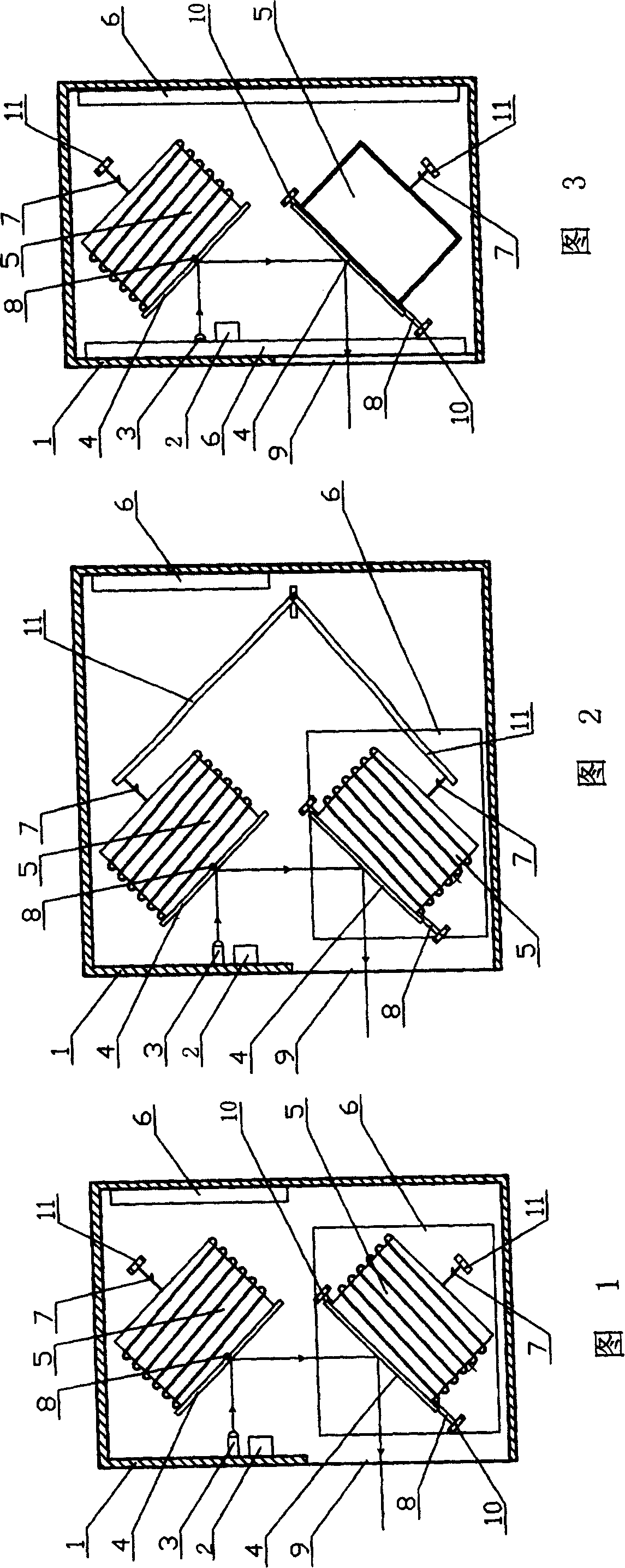
[0031] As shown in Figure 1, embodiment 1 of visible laser detector of the present invention, it comprises the housing 1 that is fixed on the vehicle, is provided with power supply unit 2, laser transmitter 3, the laser beam that laser transmitter 3 produces in housing 1 The device for oscillating scanning, the casing 1 is provided with a glass window 9 for the laser beam to emit.

[0032] The device for oscillating and scanning the laser beam generated by the laser emitter 3 includes two mirror oscillator units. The mirror vibrator unit includes a mirror 4 , a mirror rotating shaft 8 , a mirror return spring 7 , and an electromagnetic coil 5 arranged in a magnetic field; the back of the mirror 4 is fixedly connected to the electromagnetic coil 5 .

[0033] The rotation axes 8 of the two mirrors are respectively perpendicular to the lines of force of the two magnetic fields where the electromagnetic coil 5 of the mirror vibrator unit is located;

[0034] The back of the refle...


PUM


Abstract

A visible laser detector consists of shell set on vehicle, laser generator in shell, oscillation and scan unit of laser beam generated by laser generator, glass window on shell for emitting out laser beam. The said detector can make up illumination deficiency of vehicle lamp to let driver discover obstacles at far distance for raising drive - safety.

Description

technical field [0001] The present invention relates to vehicles, in particular to obstacle detectors on vehicles. Background technique [0002] As we all know, the quality of driving vision directly affects driving safety. According to statistics, more than 90% of the driver's information about traffic is obtained through vision, including the surface shape of the road, direction, traffic signal, content of traffic signs, traffic information of the vehicle, traffic flow in the opposite direction, etc. The above information is in It is easy to obtain visually during the day, but it is relatively difficult at night when there is no light, especially in harsh environments such as rain, fog or smoke. According to statistics, traffic accidents at night are 3 times that of daytime, and traffic accidents on roads with good lighting conditions are only 30% of those on roads without lighting or poor lighting. [0003] Although the headlight system of modern vehicles has made great...

Claims


Application Information

Patent Timeline
Patent Type & Authority Patents(China)
IPC IPC(8): G01S17/02G01S17/93
Inventor 陈汉汛徐达伟刘丽
Owner WUHAN UNIV OF TECH
Learn More