

Recirculation structure for turbo chargers
A technology of turbo compressor and circulation structure, which is applied to the components, mechanical equipment, engine components, etc. of the pumping device for elastic fluid, which can solve the problems of increasing the surge limit and reducing the efficiency of the compressor.
- Summary
- Abstract
- Description
- Claims
- Application Information
AI Technical Summary
Problems solved by technology
Method used
Image

Examples
Embodiment Construction
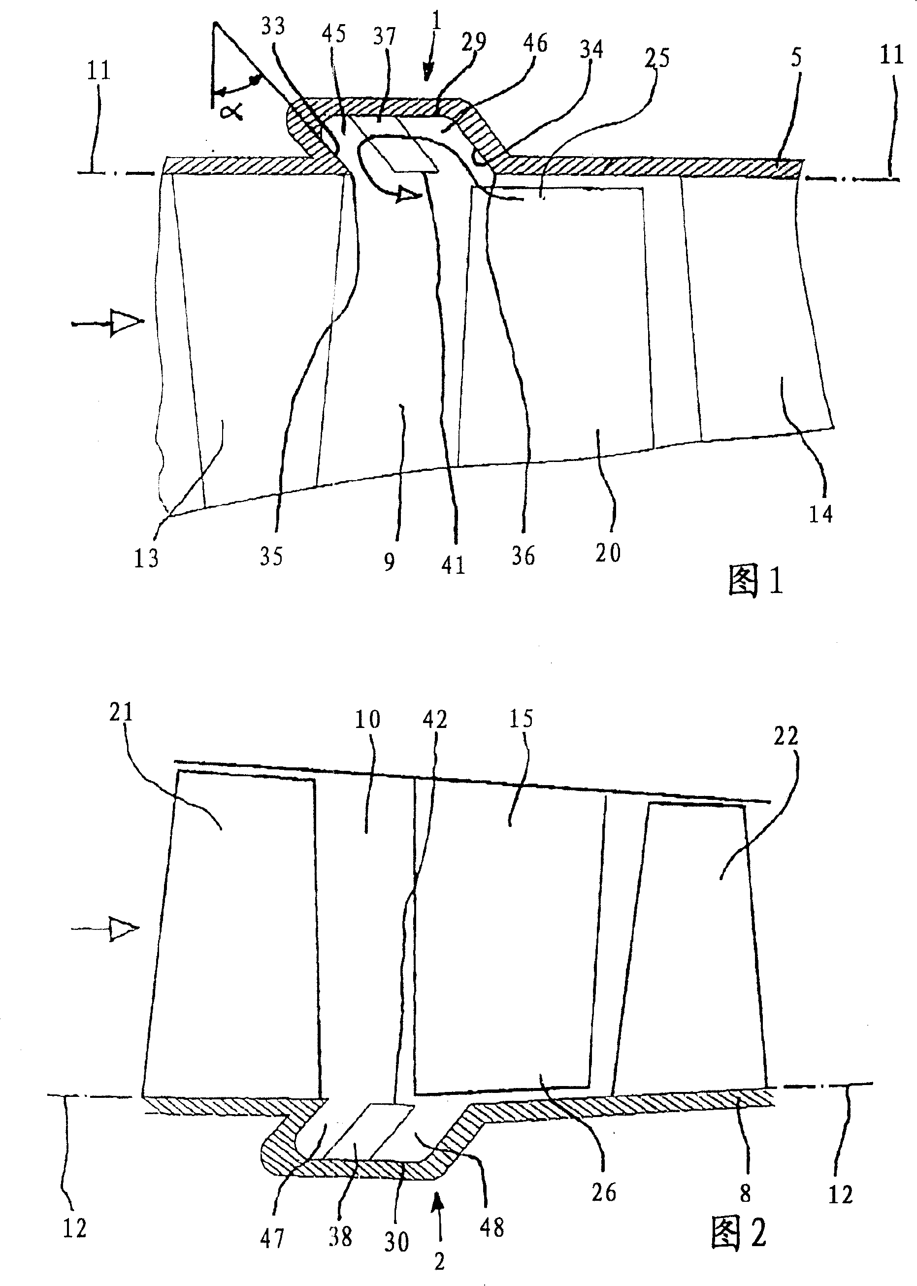
[0017] The circuit arrangement 1 shown in FIG. 1 is installed in the casing 5 of a turbocompressor and can therefore be referred to as a "casing treatment". The direction of flow in the vaned main flow duct 9 is indicated on the left by an arrow, ie it flows from left to right. In the region shown, the flow impinges first on a guide vane ring 13 , then on a rotor vane ring 20 and finally on a guide vane ring 14 again. The radial outer contour 11 of the main flow duct 9 conforms to the inner shape of the casing 5 and, in order to show this clearly, is extended by a dotted line to the left and right of the actual figure. The static circulation structure 1 interacts with the rotor blade ring 20 and is mostly located axially in front of the rotor blade ring, that is to say upstream of the rotor blade ring. The annular chamber 29 forming the circulation structure 1 together with the guide element 37 is located radially outside and adjoins the main flow duct 9 and opens into the ma...
PUM
 Abstract
Description
Claims
Application Information