Automatic change-over switch

A technology of automatic transfer switch and transmission mechanism, applied in the direction of electric switch, power device inside the switch, electrical components, etc., can solve the problems of uneven force on the handle, breakage, unreasonable force on the handle, etc., and achieve reliability and the effect of stability

Inactive Publication Date: 2008-06-25
TIANJIN BAILI ELECTRIC CO LTD
View PDF6 Cites 0 Cited by
  • Summary
  • Abstract
  • Description
  • Claims
  • Application Information

AI Technical Summary

Problems solved by technology

The disadvantage of this is that when the crank rotates, the contact position between the crank and the switch handle is constantly changing, so that the force on the handle is very uneven, and because the cranks on the left and right sides drive the automatic transfer switch to perform the circuit breaker handle action, its handle Unreasonable stress may also easily cause damage or breakage of the handle of the automatic transfer switch executive circuit breaker
And due to the large rotation angle, the inherently long switching time

Method used


Image

  • Automatic change-over switch

Examples


Embodiment Construction

[0009] In order to further understand the invention content, characteristics and effects of the present invention, the following examples are given, and detailed descriptions are as follows in conjunction with the accompanying drawings:

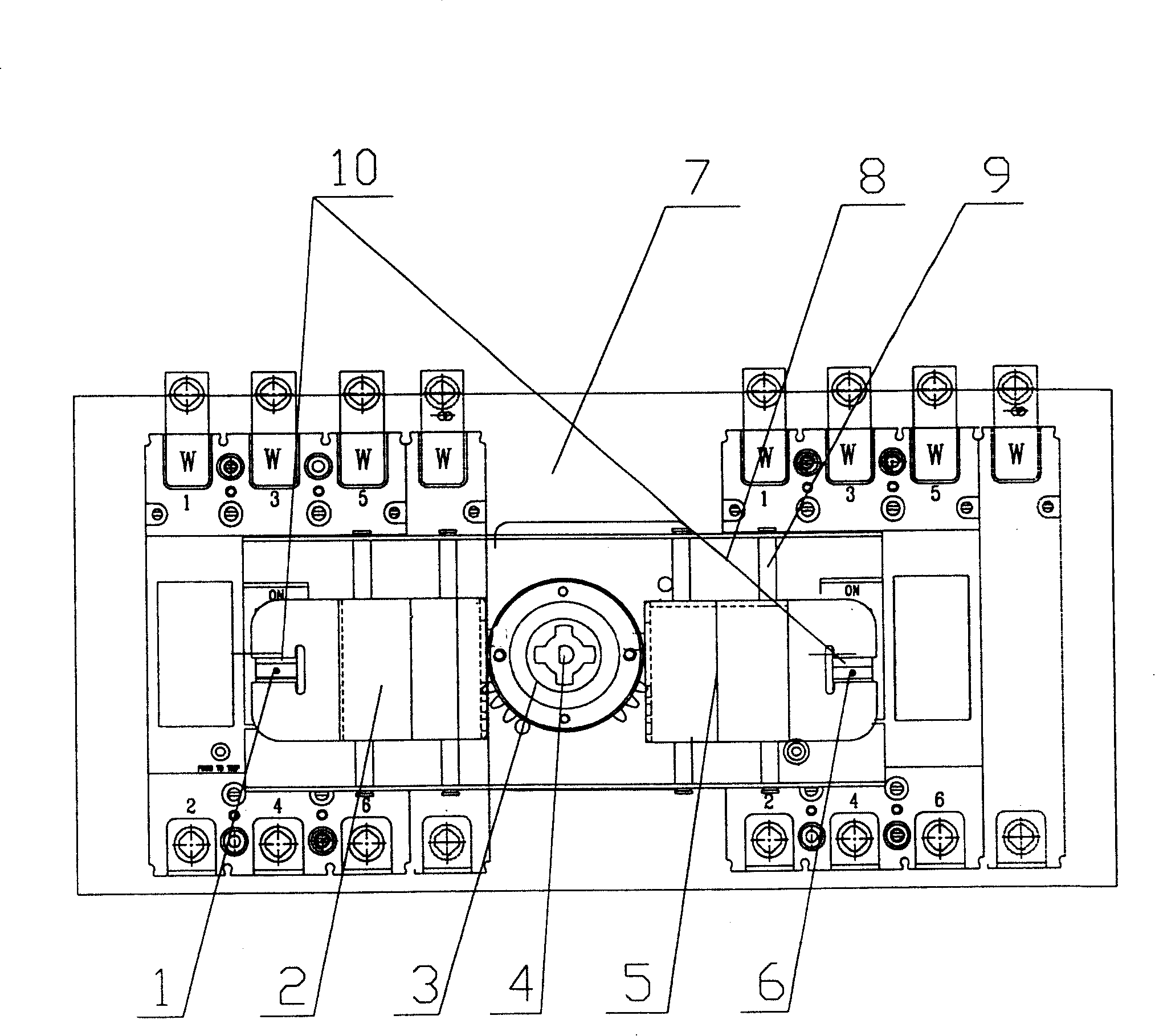
[0010] Such as figure 1 As shown, below the mounting plate 8 on the base 7, the execution circuit breaker 1, 6 is installed, and the mounting plate 8 is fixedly installed on the base 7 by four pillars, and the motor 4 is installed below the mounting plate 8 above the base 7. An incomplete gear 3 and four guide shafts 9 are fixedly installed on the plate 8 . The shaft of the motor 4 and the shaft of the incomplete gear 3 are coaxial. The incomplete gear 3 is a gear with three teeth on the 90-degree circle contained in the third and fourth quadrants of the plane where the gear is located. There are no toothed gears on the circumference in the first and second quadrants of the plane. And on two left and right slide blocks 2,5, respectively op...


PUM


Abstract

This invention relates to an automatic change-over switch, the driving part includes a motor fixed on the base and set between two executive breakers, an installing plate fixed on the base plate, two slide blocks driven by the shaft of the motor fixed on the incomplete gear on said mounting plate and set at both sides of the gear and slide along the guiding shaft, there are teeth clutched with the gear on the slide blocks and bayonets combining with the handles of the master and stand-by breakers, which combines the general motion of the incomplete gear with the rack driving of the gear very well to realize the separation and combination motion separately for the two executive breakers.

Description

Technical field [0001] The invention belongs to an electric switch, in particular to an automatic transfer switch. Background technique [0002] In order to realize the on-off switching of two executive circuit breakers, the currently known automatic transfer switch transmission mechanism adopts the cranks on both sides driven by the drive disc, and the drive disc rotates under the drive of the motor, and the cranks on both sides are respectively Make a circular motion to drive the two executive circuit breaker handles to close and open. The disadvantage of this is that when the crank rotates, the contact position between the crank and the switch handle is constantly changing, so that the force on the handle is very uneven, and because the cranks on the left and right sides drive the automatic transfer switch to perform the circuit breaker handle action, its handle Unreasonable stress may also easily cause damage or breakage of the handle of the automatic transfer switch ex...

Claims


Application Information

Patent Timeline
Patent Type & Authority Patents(China)
IPC IPC(8): H01H3/26H01H3/54
Inventor 梁燕高云旭高辉郭玲张莉黄艳杰王喆张瑞平
Owner TIANJIN BAILI ELECTRIC CO LTD
Why Eureka
Try Eureka