

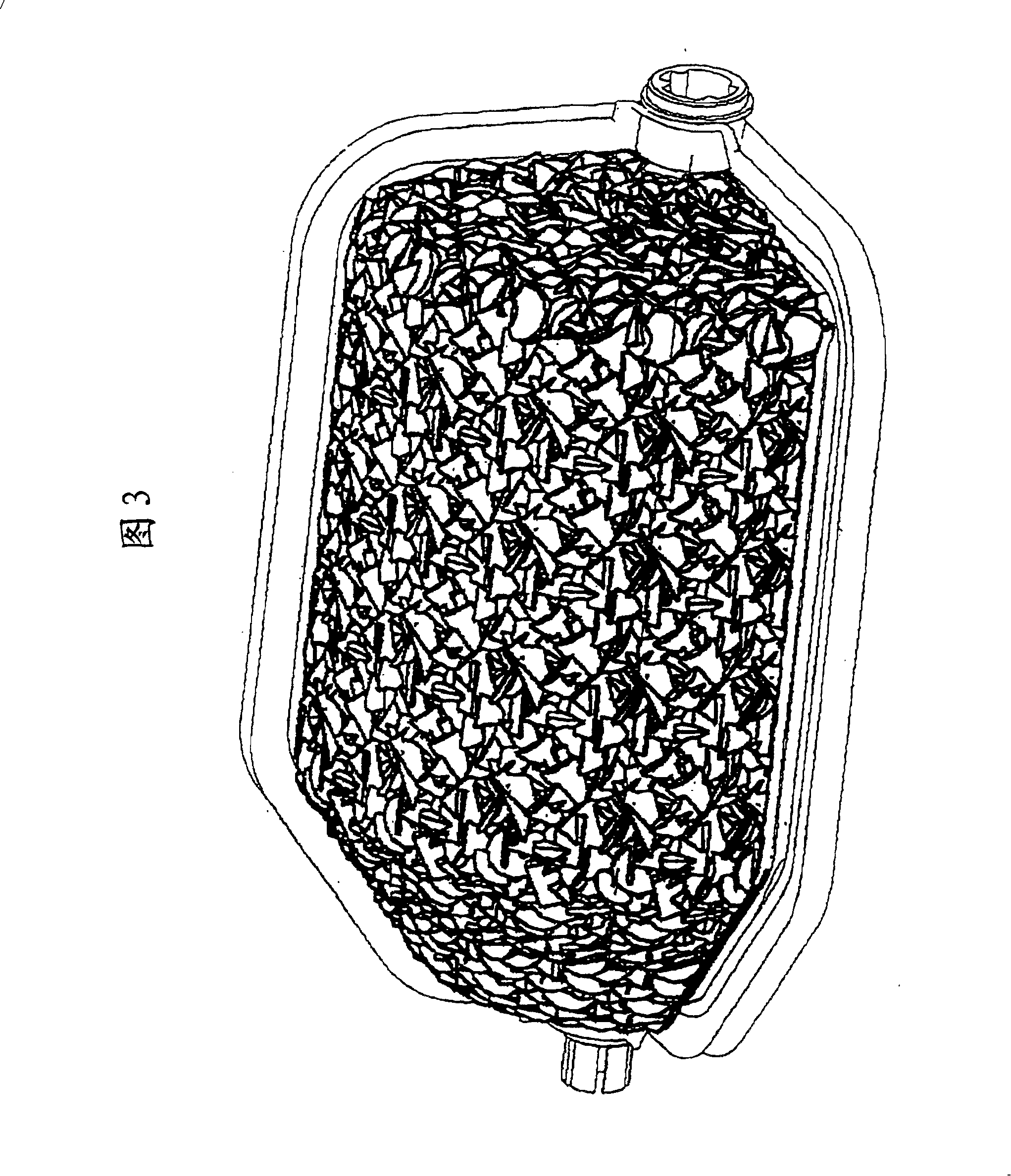
Cylindrical flap with structured rough surfaces
An air flow control device, air technology, used in transportation and packaging, air handling equipment, heating/cooling equipment, etc., can solve problems such as insufficient noise reduction effect
- Summary
- Abstract
- Description
- Claims
- Application Information
AI Technical Summary
Problems solved by technology
Method used
Image

Examples
Embodiment Construction
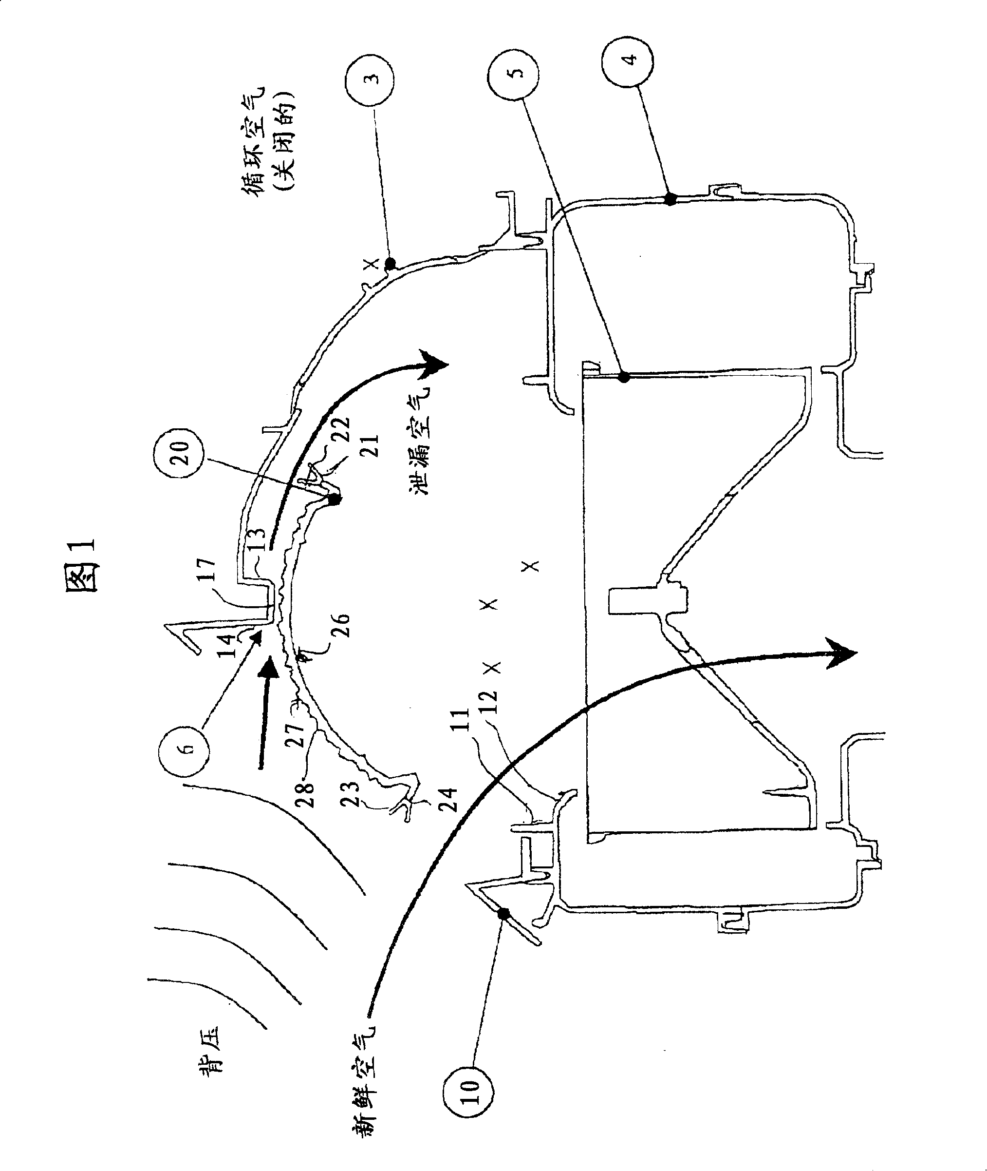
[0021] 1 shows a sectional view of an air inlet housing with a fresh air / circulating air control device for a heating, ventilation and / or air conditioning system of a vehicle, which is an airflow control device according to the invention A preferred application of .
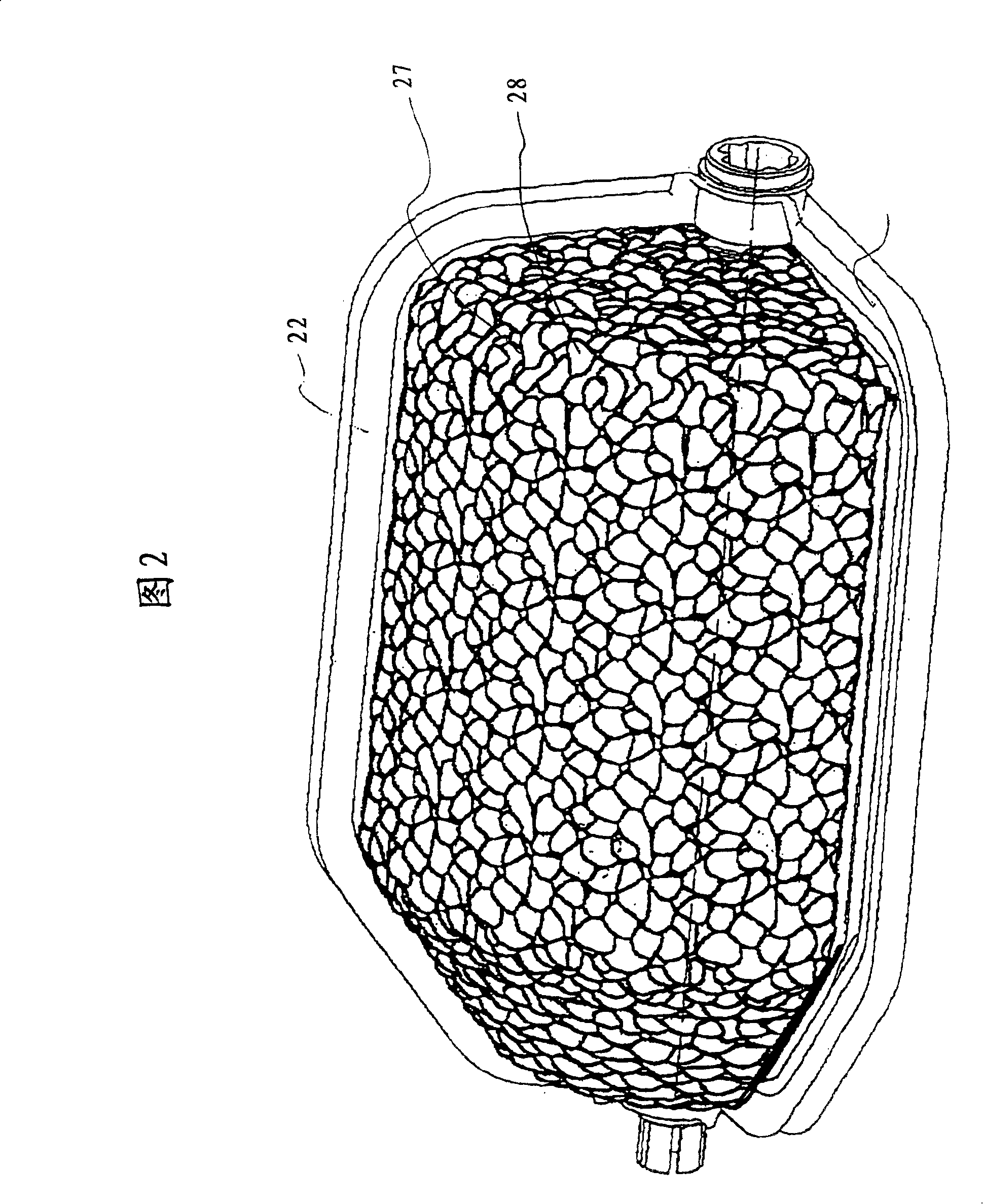
[0022] The air flow control device comprises a cylindrical or shell-type valve 20 and an air channel which is delimited by the air inlet housing 10 , in the embodiment shown the fresh air supply channel opening is shown. The device shown conveys fresh or recirculated air into the vehicle interior by means of a blower, indicated only by fan wheel 5 in the figure. For closing / cutting off the fresh air supply, a cylinder valve or shell valve 20 is provided in a known manner, which has a first surface which can sealingly engage with the first surface sections 11 , 12 , 13 , 14 of the air channel Sections 21, 22, 23, 24. Furthermore, in the embodiment shown, the air channel also includes a second surface section 17 ...
PUM
| Property | Measurement | Unit |
|---|---|---|
| Depth | aaaaa | aaaaa |
Abstract
Description
Claims
Application Information