Internal anti-icing device of fanjet

A technology for turbofan engines, icing conditions, applied in the direction of engine components, machines/engines, mechanical equipment, etc., which can solve the necessary performance loss and other problems, and achieve the effect of eliminating performance degradation, reducing ice accumulation, and reducing threats

Active Publication Date: 2008-09-17
GENERAL ELECTRIC CO
View PDF6 Cites 7 Cited by
  • Summary
  • Abstract
  • Description
  • Claims
  • Application Information

AI Technical Summary

Problems solved by technology

However, the necessary performance loss to the engine cycle due to the amount of air from the exhaust compressor used to de-ice the leading edge of the boost splitter must be taken into account
This loss is a result of the work done by the compressor on the ambient atmosphere to pressurize it and thus melt the ice from the splitter head, which cannot be used by the turbomachinery components to generate thrust

Method used


Image

  • Internal anti-icing device of fanjet
  • Internal anti-icing device of fanjet
  • Internal anti-icing device of fanjet

Examples


Embodiment Construction

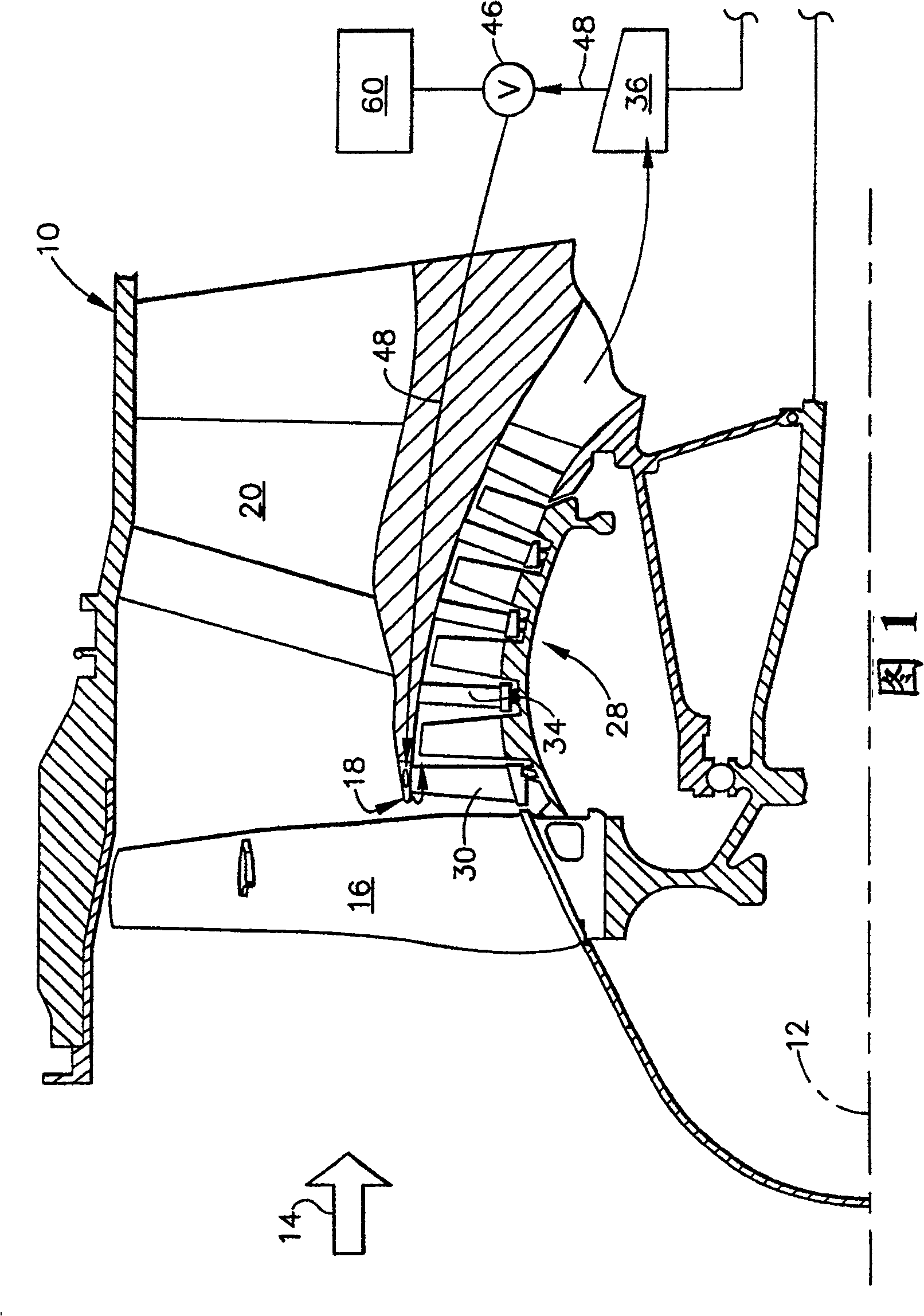
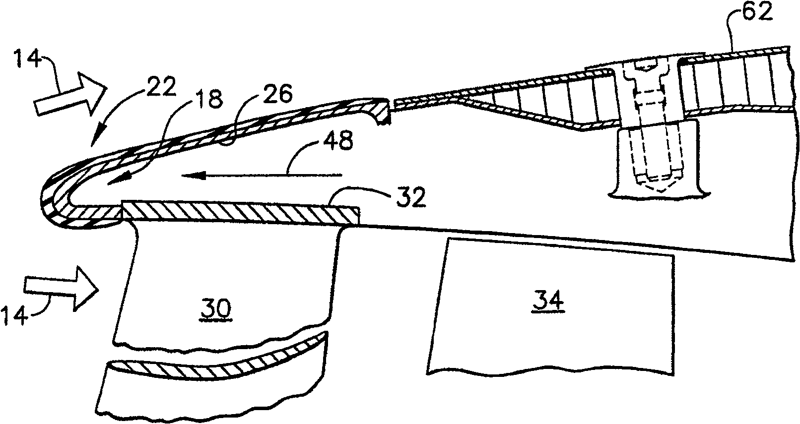
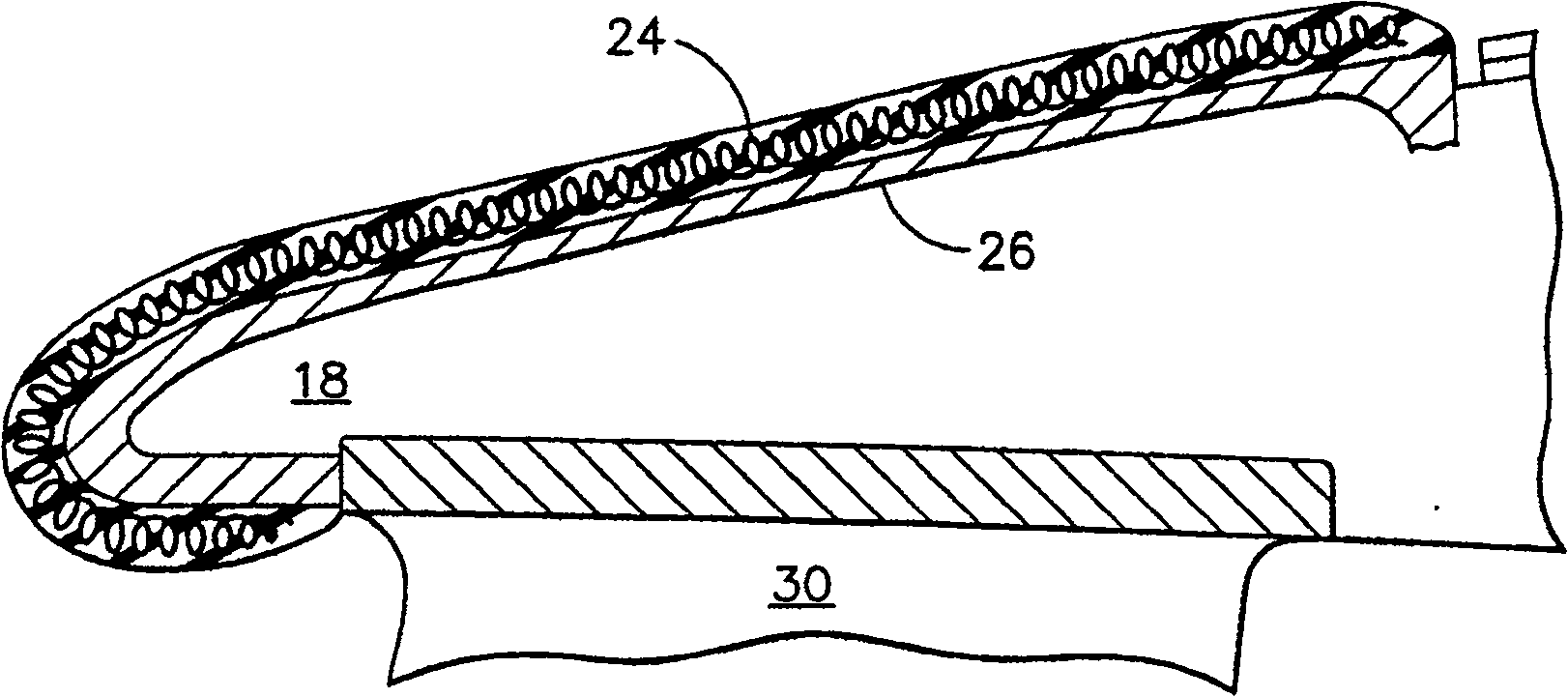
[0031] Referring to FIG. 1, there is shown a portion of a high split turbofan gas turbine engine 10 configured to operate as an aircraft (not shown) during takeoff, cruise at altitude, descent, and landing during respective flight envelope operations. shown) to provide power. The engine is axisymmetric about a longitudinal or axial center axis 12 and includes an air intake 14 at its forward end to receive ambient atmosphere 14 . Ambient atmosphere 14 first engages a row of fan rotor blades 16 . The air discharged from the fan blades is divided concentrically by the annular splitter head 18 to flow respectively through an annular bypass duct 20 surrounding the splitter and a low pressure or booster compressor 22 inside the splitter.

[0032] The basic engine configuration shown in Figure 1 is conventional and has been in commercial operation in this country for many years, although the present invention is not applied. The bypass duct 20 is surrounded by a partially shown con...


PUM


Abstract

A system and method are provided for preventing the formation of ice on or removing ice from an internal surface of a turbofan engine. A splitter region (18), associated with a booster compressor of the turbofan engine, is identified. The splitter region (18) has surfaces internal to the turbofan engine subject to inlet icing conditions. A resin (26) is molded along a leading edge of the splitter region (18), and electric coils (24) are installed within the resin (26) to prevent ice build-up on the splitter region (18) or to remove ice from the splitter region (18) during icing conditions.

Description

technical field [0001] This invention relates to gas turbine engines, and more particularly to deicing arrangements therein. Background technique [0002] During flight and / or grounding, an aircraft may encounter atmospheric conditions that cause icing to form on the airfoils and other surfaces of the aircraft. If the accumulated ice is not removed, it can change the aerodynamic profile of the icy components, adversely affecting the aerodynamic performance of the engine. Therefore, the engine of the aircraft is required to have the ability to work in the icing environment to meet the requirements of the Federal Aviation Administration. [0003] Ice accumulation is typically treated by providing the affected compressor airfoil with increased strength to avoid or reduce problems caused by ice release. Commercial engines have been able to mitigate operational problems caused by ice accumulation by increasing air idle or ground idle speeds without violating thrust constraints....

Claims


Application Information

Patent Timeline
Patent Type & Authority Patents(China)
IPC IPC(8): F02C7/047F01D25/02F01D17/16F02K3/06
CPCF02C7/047Y02T50/672F01D25/02Y02T50/60Y10T29/49401
Inventor A·R·瓦迪亚R·G·霍尔姆
Owner GENERAL ELECTRIC CO
Why Eureka
Try Eureka