
Buried full medium optical cable

An all-dielectric and optical cable technology, applied in the direction of fiber mechanical structure, etc., can solve the problems of unreachable, poor lateral pressure resistance, difficulty in meeting the mechanical performance requirements of direct burial, etc.

Active Publication Date: 2008-09-24
ZHEJIANG FUCHUNJIANG PHOTOELECTRIC SCI & TECH
View PDF3 Cites 0 Cited by
  • Summary
  • Abstract
  • Description
  • Claims
  • Application Information

AI Technical Summary

Problems solved by technology

The non-metallic optical cables in the prior art have poor tensile and lateral pressure resistance (failure to meet the requirements of direct-buried optical cables), and it is difficult to meet the mechanical performance requirements of direct-buried optical cables

Method used


Image

  • Buried full medium optical cable

Examples


Embodiment

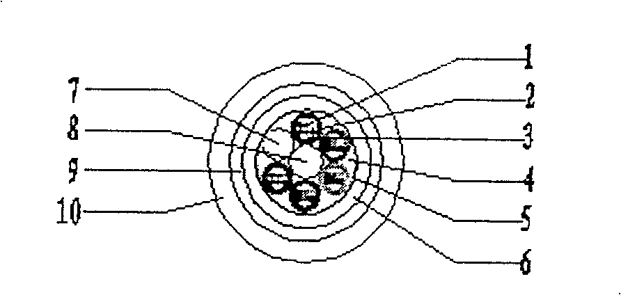
[0010] Example: such as figure 1 As shown, the cable core adopts a 1+6 structure with 30 cores, that is, 5 bundle tubes 2 (6 cores / tube) + 1 filling rope 7 and a central reinforcement 8. The central reinforcement in this embodiment is FRP (glass Fiber-reinforced plastic round rod), the modulus of elasticity of FRP is 50GPa, the diameter is 2.1mm, each bundle tube contains 6 optical fibers 1, the excess length of the fiber in the bundle tube is 0.6-1.0‰, the bundle tube in the cable core adopts SZ stranding, twisted The joint pitch / twisting angle is 60-70mm / 10π, and the glass fiber yarn 9 is used as a tensile element for the outer wrapping of the cable core. Due to the reasonable excess length of the optical fiber and the small twisting pitch, the present invention makes the performance of the optical cable normal in direct burial environment, high tensile strength and other severe mechanical performance requirements and high and low temperature operation; the outer longitudina...


PUM


Abstract

The present invention relates to a plow-in al-medium optical cable. It is characterized by that the optical cable centre reinforcement adopts non-metal glass fibre reinforced plastic round pipe, the optical fibre in the bundle pipe is longer than bundle pipe, the bundle pipe in cable core adopts SZ twisted mode, the exterior of cable core is covered with polyethylene inner jacket whose thickness is 1.0-1.2mm, then covered with non-metal glass fibre yarn, and finally covered with polyethylene outer jacket whose thickness is 2.0 mm.

Description

Technical field: [0001] The invention relates to a communication optical cable, in particular to the invention of a direct-buried optical cable suitable for strong electric field, anti-strong electromagnetic interference, national defense communication lines and the like. Background technique [0002] The optical cables used in strong electric fields, high signal shielding requirements, and national defense communication lines are directly buried underground, so the optical cables themselves should have the characteristics of high tensile strength, lateral pressure resistance, and no electromagnetic interference. Ordinary optical cables used for direct buried line communication require high tensile strength, lateral pressure resistance and other properties, but they are not suitable for direct buried environments requiring strong electric fields. The non-metallic optical cables in the prior art have poor tensile and lateral pressure resistance (failing to meet the requiremen...

Claims


Application Information

Patent Timeline
Patent Type & Authority Patents(China)
IPC IPC(8): G02B6/44
Inventor 张万春祝冬军薄崇飞方伟栋
Owner ZHEJIANG FUCHUNJIANG PHOTOELECTRIC SCI & TECH
Learn More