Embedded type microscopy digital camera

A digital camera, embedded technology, applied in microscopes, optics, instruments, etc., can solve the problems of discarding the original binocular microscope, unable to solve the camera device, etc., and achieve the effect of reasonable design, compact and accurate structure

Inactive Publication Date: 2008-09-24
JIANGSU JIEDA SOFTWARE ENG
View PDF9 Cites 0 Cited by
  • Summary
  • Abstract
  • Description
  • Claims
  • Application Information

AI Technical Summary

Problems solved by technology

According to the above situation, due to the limitation of the conjugate distance length of the old-fashioned binocular microscope, it is impossible to solve the application of the camera device into the computer processing technology, and the trinocular microscope is faced with the practical problems of purchasing funds and discarding the original binocular microscope

Method used


Image

  • Embedded type microscopy digital camera
  • Embedded type microscopy digital camera

Examples


Embodiment Construction

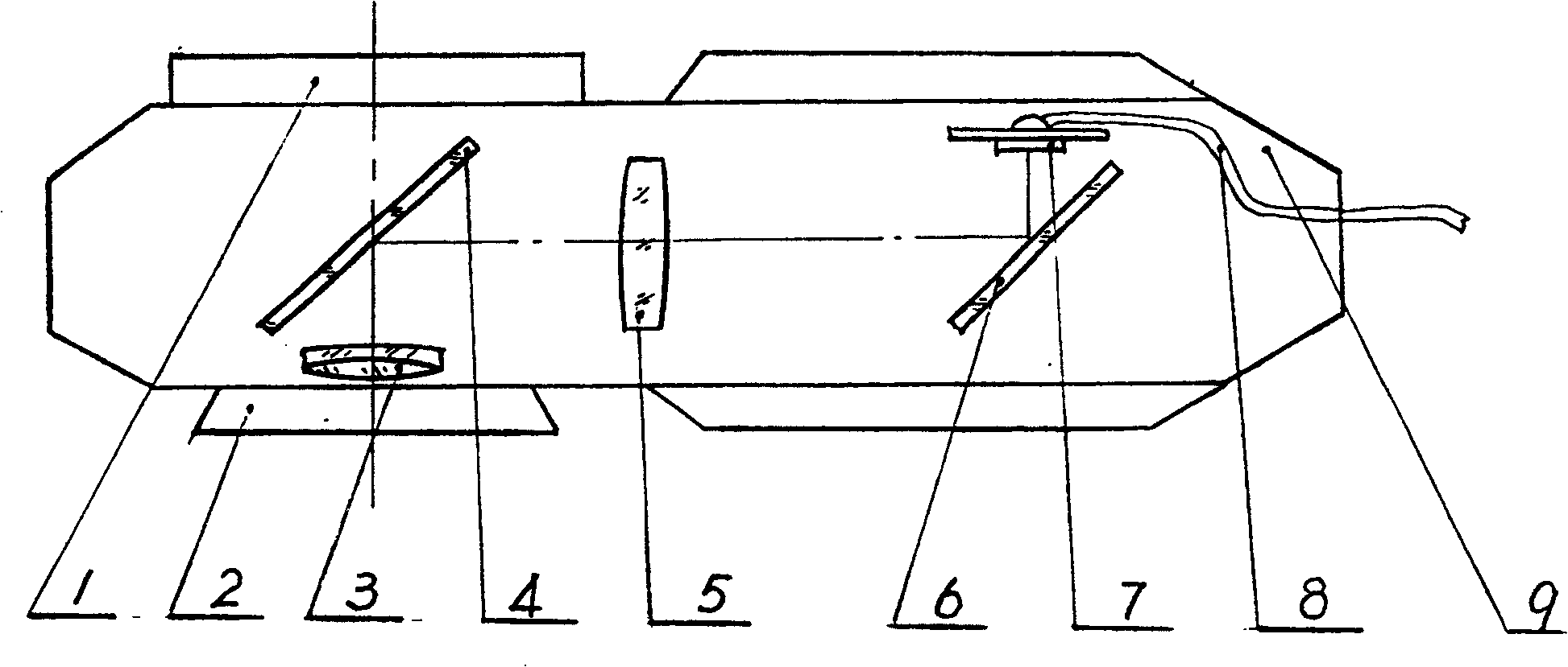
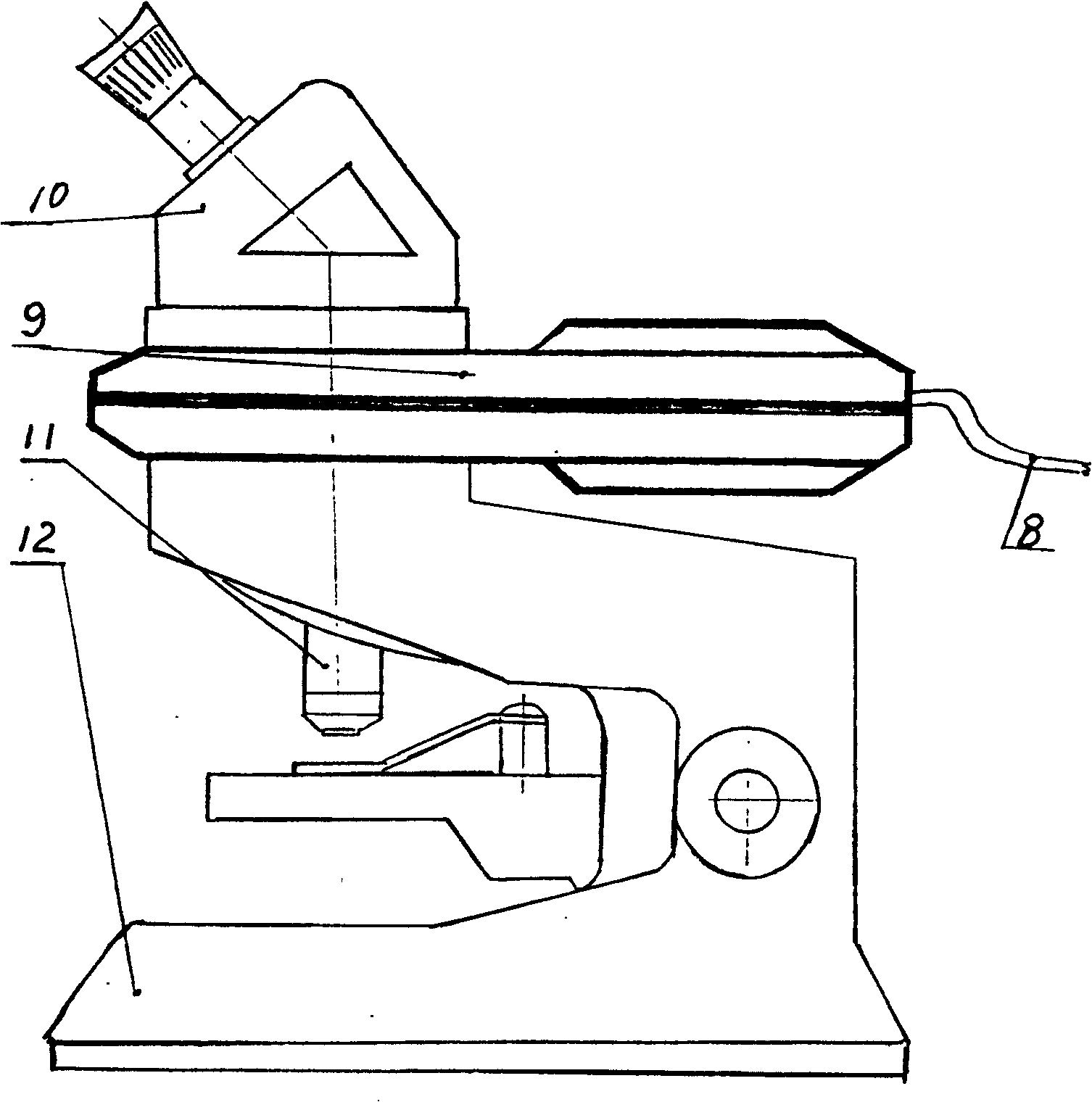
[0011] Refer to attached Figure 1~2 , The structure of the embedded microscopic digital camera includes a camera housing 9, an upper interface 1, a lower interface 2, a front objective lens 3, a transflective lens 4, an imaging objective lens 5, a reflector 6, an imaging target core 7, and a USB video line 8. The upper part of the camera housing 9 is provided with an upper interface 1 to be connected with the microscope eyepiece 10, the lower part of the camera housing 9 is provided with a lower interface 2 to be connected with the microscope objective lens 11, and the upper part of the lower interface 2 of the camera housing 9 is provided with a front objective lens 3, through which the front The objective lens 3 changes the original converging beam into a parallel beam, thereby changing the total length of the optical path and the optical characteristics of the optical system. The device is installed between the transflector sheet 4 and the reflector 6, and the camera targe...


PUM


Abstract

The invention relates to a flush type micro display diagram camera which is matched with microscope in the field of biology, medicine, mineralogy, metallography and micro-melting point of micro camera technology. Its structure comprises camera cave, upper interface, lower interface, auxiliary object lens, reversed lens, camera object lens, reflex mirror, camera reflecting target and USB video line, wherein upper interface is posited on the upper parts of camera cave and connected with microscope ocular; auxiliary object lens changes elementary syntaxis beam into parallelism beam; reversed lens is posited in front of auxiliary object lens; reversed lens changes the beam into two beams and one beam enters eye-glass, while the other beam enters camera system; reflex mirror is posited in front of camera reflecting target; camera object lens is posited between reversed lens and reflex mirror; camera reflecting target is connected with USB video line.

Description

technical field [0001] The embedded microscopic digital camera of the present invention relates to a microscopic digital camera matched with a microscope, which is used for microscopic photography in related fields such as biology, medicine, mineralogy, metallography and melting point microscopy in microscopic photography technology. Background technique [0002] At present, most of the various microscopes used in various disciplines are binocular microscopes. If a camera is used to obtain images in the visual system, it will not be possible. [0003] Due to the application of micro-camera technology, domestic manufacturers have developed a beam-splitter prism that is synchronized with the visual system and separates a beam of light from the front side of the visual image to image in the camera system. The eyepiece imaging device forms images in the camera (analog signal). According to the above-mentioned status quo, due to the limitation of the conjugate distance length of...

Claims


Application Information

Patent Timeline
Patent Type & Authority Patents(China)
IPC IPC(8): G02B21/36
Inventor 姜建明杨永华李德胜牛志荣
Owner JIANGSU JIEDA SOFTWARE ENG
Why Eureka
Try Eureka