Eureka AIR delivers breakthrough ideas for toughest innovation challenges, trusted by R&D personnel around the world.

Pressurized soluble salt continuous vulcanizing device

A technology of dissolving salt and vulcanizing tubes, which is applied in the manufacture of electrical components, circuits, cables/conductors, etc., which can solve problems such as inconvenient operation, easy damage, and limitation of processing specifications, and achieve high heat energy utilization, reduce energy consumption, and operate convenient effect

Inactive Publication Date: 2008-10-15
吕金海
View PDF4 Cites 0 Cited by
  • Summary
  • Abstract
  • Description
  • Claims
  • Application Information

AI Technical Summary

Problems solved by technology

The liquid salt in the salt storage tank of the above-mentioned device is directly pressed into and filled with the vulcanization pipe by gravity. Although it overcomes the shortcoming that the pipeline pump of the previous continuous vulcanization device needs to work continuously and is easily damaged, it still has the following disadvantages: 1. The above-mentioned device During operation, the cable bends in an "S" shape when passing the transmission wheel, so it is only suitable for processing small-diameter cables, and the processing specifications are limited; It is completed in the salt storage tank. If the cable is disconnected and wiring is required, all the dissolved salt in the salt storage tank needs to be taken out. At this time, the dissolved salt in the salt storage tank is at a high temperature, so the operation is very inconvenient; 3. Cable During the vulcanization process, the dissolved salt will be lost, and it is necessary to add salt to the salt storage tank from time to time. Since the above-mentioned device can only rely on the experience and judgment of the staff, there may be a problem that it cannot be added in time, and the operation is not good. convenient

Method used


Image

  • Pressurized soluble salt continuous vulcanizing device
  • Pressurized soluble salt continuous vulcanizing device
  • Pressurized soluble salt continuous vulcanizing device

Examples


Embodiment 1

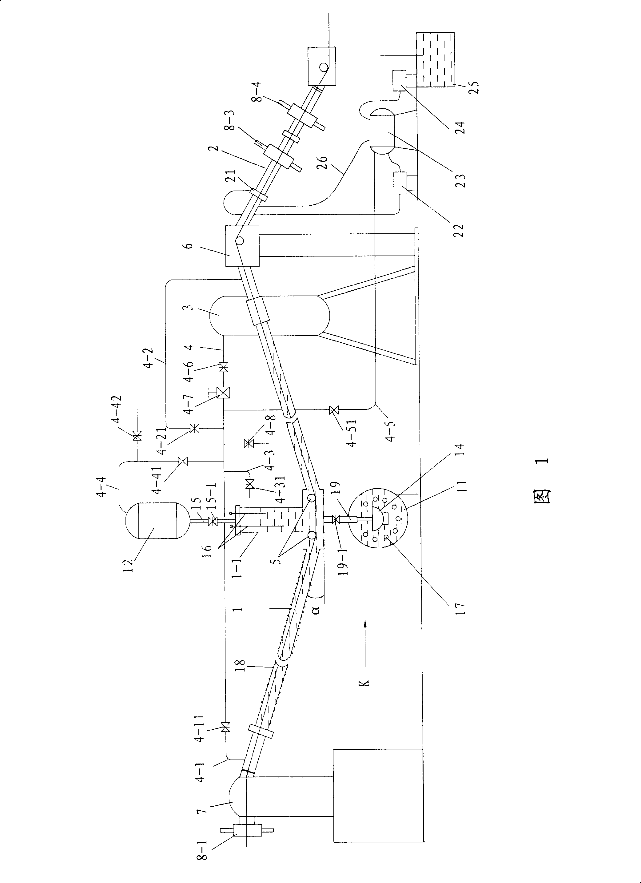
[0022] See Figure 1 and figure 2 , the present invention includes vulcanization device, cooling device and compressed air supply device.

[0023] The vulcanization device includes a vulcanization pipe 1 and a salt storage assembly.

[0024] The vulcanization tube 1 is a "V"-shaped curved tube with both ends higher than the middle, and the inclination angle α of the curved tube is between 1°-15°, for example, 1.5°-2°. The angle of the inclination α is related to the length of the vulcanizing tube 1. If the length is longer, the inclination α can be smaller, but there is no strict requirement. The outside of the vulcanization tube 1 is wound with a heating heating wire 18, which realizes regional temperature control, and the outside of the heating heating wire 18 is provided with an insulation layer (not shown in the figure). The vulcanization pipe 1 is provided with a cable transmission wheel 5 .

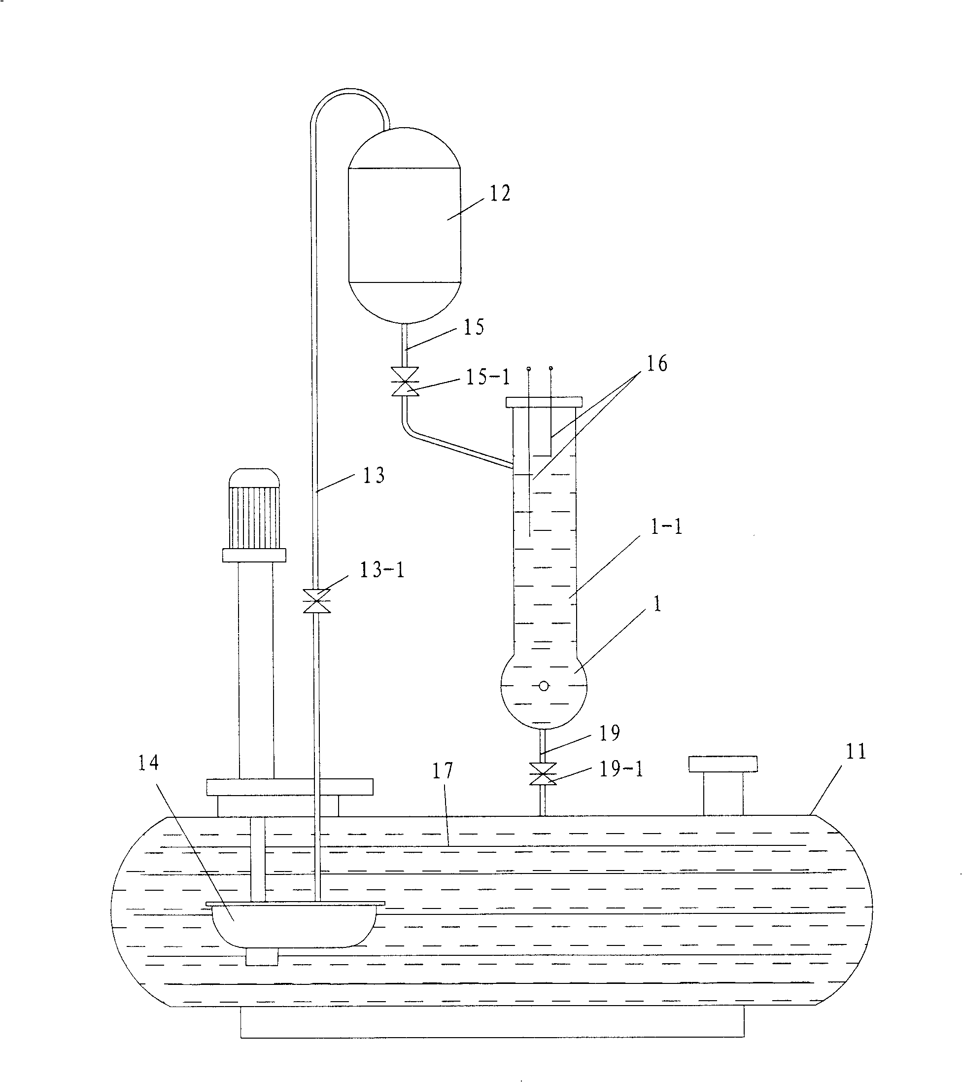
[0025] The salt storage assembly includes a horizontal salt storage tank 11 a...

Embodiment 2

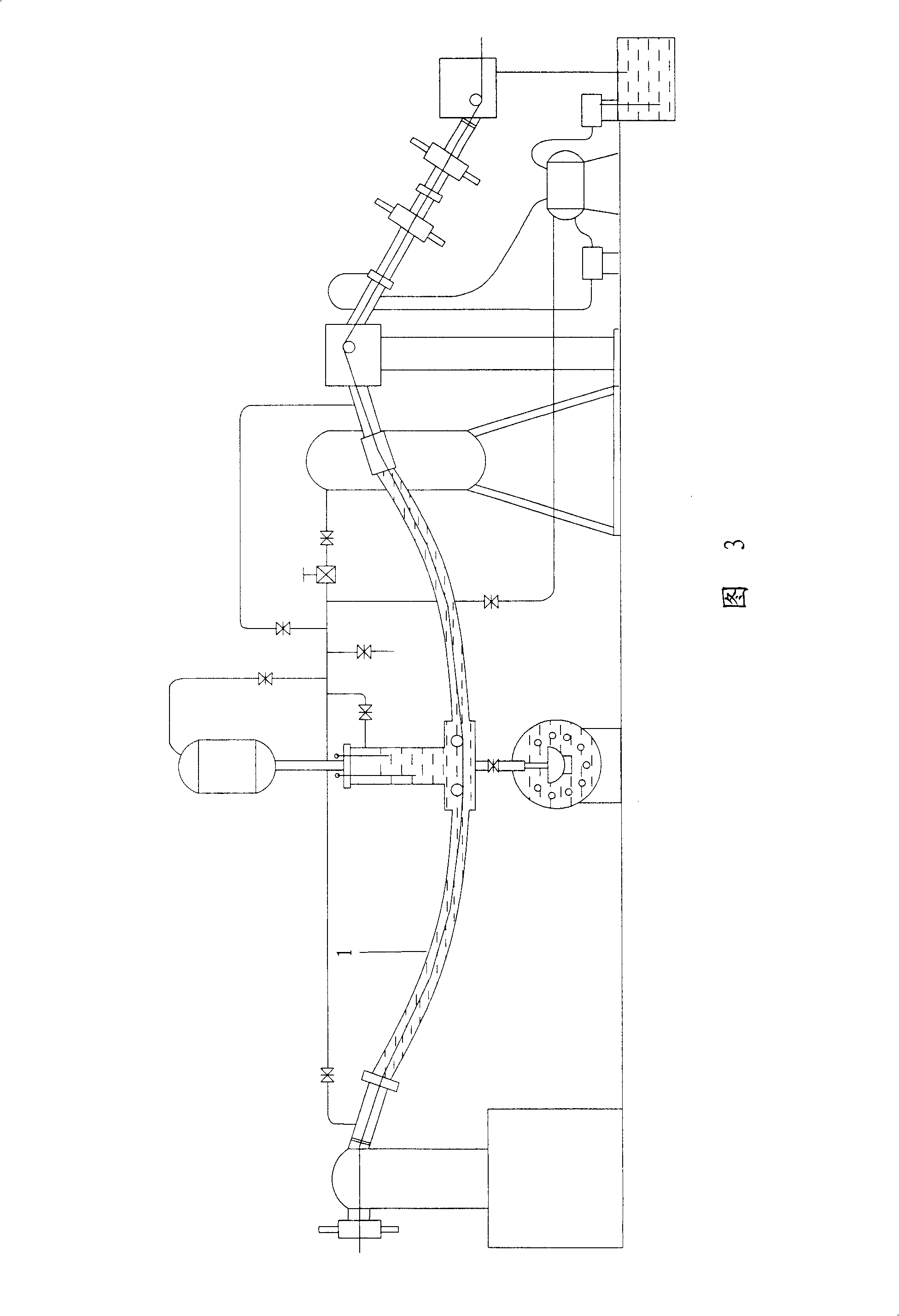
[0032] See Fig. 3, the difference between this embodiment and embodiment 1 is that the vulcanization tube 1 is arc-shaped, and the others are the same.


PUM


Abstract

The invention relates to a device for continuously vulcanizing fused salt, wherein it comprises vulcanizing device, cooler and compression air feeder. The vulcanizing tube of vulcanizing device is curved; the slat storage element comprises salt pot, fused salt pump; the vulcanizing tube is connected to the salt pot; the salt pump feeds the fused salt of pot into assist salt pot connected to the liquid groove of vulcanizing tube; the liquid groove has liquid level controller. The vulcanizing process is completed in vulcanizing tube; the cable straightly passes the vulcanizing tube. The invention can be used on variable cables; the middle of vulcanizing tube is filled with fused salt always; the pump will work when needs to add salt. And the controller can detect the salt condition in vulcanizing tube to feed salt on time. When the cable is broken, the fused salt of vulcanizing tube can be completely discharged into salt pot.

Description

technical field [0001] The invention relates to a pressurized molten salt continuous vulcanization device. Background technique [0002] It is a common method to vulcanize cables by using a continuous vulcanization device with pressurized molten salt. Chinese patent ZL03278259.4 discloses a "continuous vulcanization device for pressurized molten salt for manufacturing cables", which includes a vulcanization device for cables, a cooling device, and a compressed air supply device. The salt storage device in the vulcanization device includes a salt storage tank arranged on the frame, the lower part of the salt storage tank is connected with the vulcanization pipe, the upper space of the salt storage tank is connected with the water cooling pipe, and the upper space of the salt storage tank is respectively passed through The compressed air pipeline is connected with the upper space of the vulcanization pipe and the compressed air supply device, and the transmission wheel of the...

Claims


Application Information

Patent Timeline
Patent Type & Authority Patents(China)
IPC IPC(8): B29C35/02H01B13/00
Inventor 吕金海仇明官龚如生
Owner 吕金海
Why Eureka
Eureka Blog
Learn More