Control system of well mouth release valve

A technology of control device and safety valve, which is applied in wellbore/well valve device, wellbore/well components, earth-moving drilling, etc., can solve problems such as inability to achieve, achieve pollution prevention, protect oil and gas resources, and protect wellhead equipment and the effect of pipeline safety

Active Publication Date: 2008-10-15
深圳市弗赛特科技股份有限公司
View PDF4 Cites 0 Cited by
  • Summary
  • Abstract
  • Description
  • Claims
  • Application Information

AI Technical Summary

Problems solved by technology

This feature cannot be implemented in existing devices

Method used


Image

  • Control system of well mouth release valve

Examples


Embodiment Construction

[0013] The present invention will be described in further detail below in conjunction with the accompanying drawings and specific embodiments.

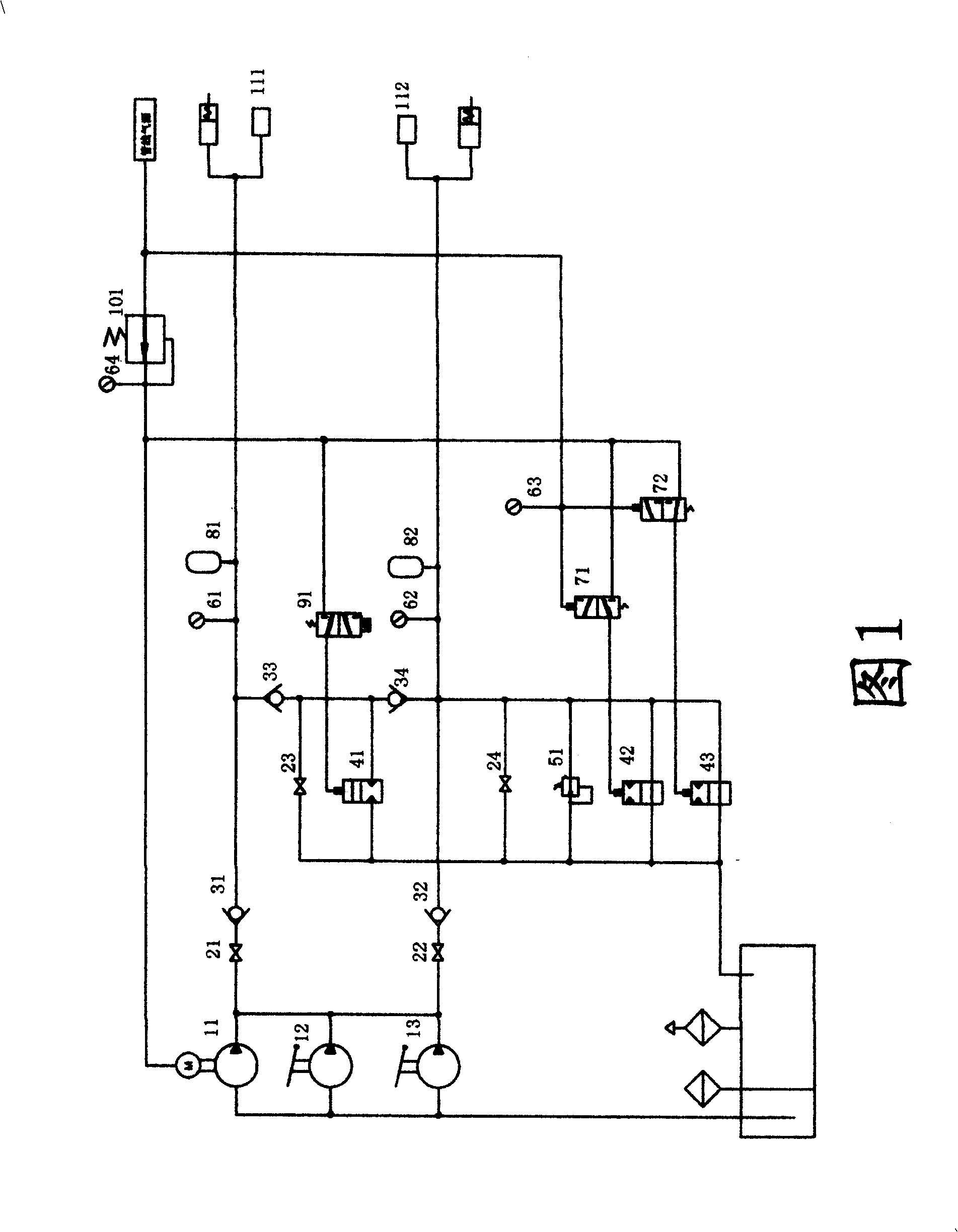
[0014] Please refer to Fig. 1, a wellhead safety valve control device, including a high-pressure pump 11, a manual pump 12, 13, a ground safety valve control circuit, the ground safety valve control circuit includes a stop valve 22, a one-way valve 32, a pressure gauge 62 , accumulator 82, the four are connected in sequence, and a relief valve 51 is set between the check valve 32 and the pressure gauge 62, one end of the shut-off valve 22 is connected to the high-pressure pump 11, and one end of the accumulator 82 is connected to the ground safety valve. The shut-off valve 22 is a high-pressure needle valve, the high-pressure pump 11 is a pneumatic booster pump, and is connected to the pipeline gas source, and a high-pressure needle is set between the check valve 32 and the pressure gauge 62 in the ground safety valve control circuit. ...


PUM


Abstract

The invention relates to a well safety valve control system, which comprises: an air-powered pressurizing pump and a ground safety valve control circuit, wherein said ground safety valve control circuit comprises one high-pressure needle valve, one-way valve, a pressure meter, and an energy accumulator; one overflow valve is between the one-way valve and the pressure meter; one end of high-pressure needle valve is connected to the air-powered pressurizing pump; one end of energy accumulator is connected to the ground safety valve and connected to the air source; another high-pressure needle valve is between the one-way valve and the pressure meter; the under-well safety valve control circuit is between the air-powered pressurizing pump and the under-well safety valve; said circuit comprises one high-pressure needle valve, one-way valve, pressure meter, and energy accumulator which are connected; another branch is between the one-way valve and the pressure meter, whose another end is connected between the one-way valve and the pressure meter; said branch has two one-way valves; one high-pressure needle valve is between two one-way valves.

Description

technical field [0001] The invention relates to a device for extracting oil or natural gas from deep wells, in particular to a well head safety valve control device for oil or natural gas. Background technique [0002] At present, the opening pressure of the safety valves of most oil and gas wells in Northwest my country is around 15,000 psi (100 MPa), while the maximum working pressure of the traditional hydraulic devices used in existing devices can only reach 5,000 psi (35 MPa), which cannot meet the operating requirements. Since the use site is a flammable and explosive place with extremely high concentration of natural gas, the explosion-proof level is required to be above EXD II BT4. The existing devices use electro-hydraulic pumps and solenoid valves, which will heat up the system and easily generate electric sparks during operation. Serious potential safety hazards, and the existing technology can only control the surface safety valve, but cannot control the downhole...

Claims


Application Information

Patent Timeline
Patent Type & Authority Patents(China)
IPC IPC(8): E21B33/03E21B34/02
Inventor 何建辉
Owner 深圳市弗赛特科技股份有限公司
Why Eureka
Try Eureka