Control system of well mouth release valve

A control system and safety valve technology, applied in wellbore/well valve devices, wellbore/well components, earthwork drilling, etc. The effect of protecting oil and gas resources

Active Publication Date: 2007-02-07
深圳市弗赛特科技股份有限公司
View PDF0 Cites 24 Cited by
  • Summary
  • Abstract
  • Description
  • Claims
  • Application Information

AI Technical Summary

Problems solved by technology

However, this function cannot be realized in the existing system

Method used


Image

  • Control system of well mouth release valve

Examples


Embodiment Construction

[0014] The present invention will be further described in detail below with reference to the drawings and specific embodiments.

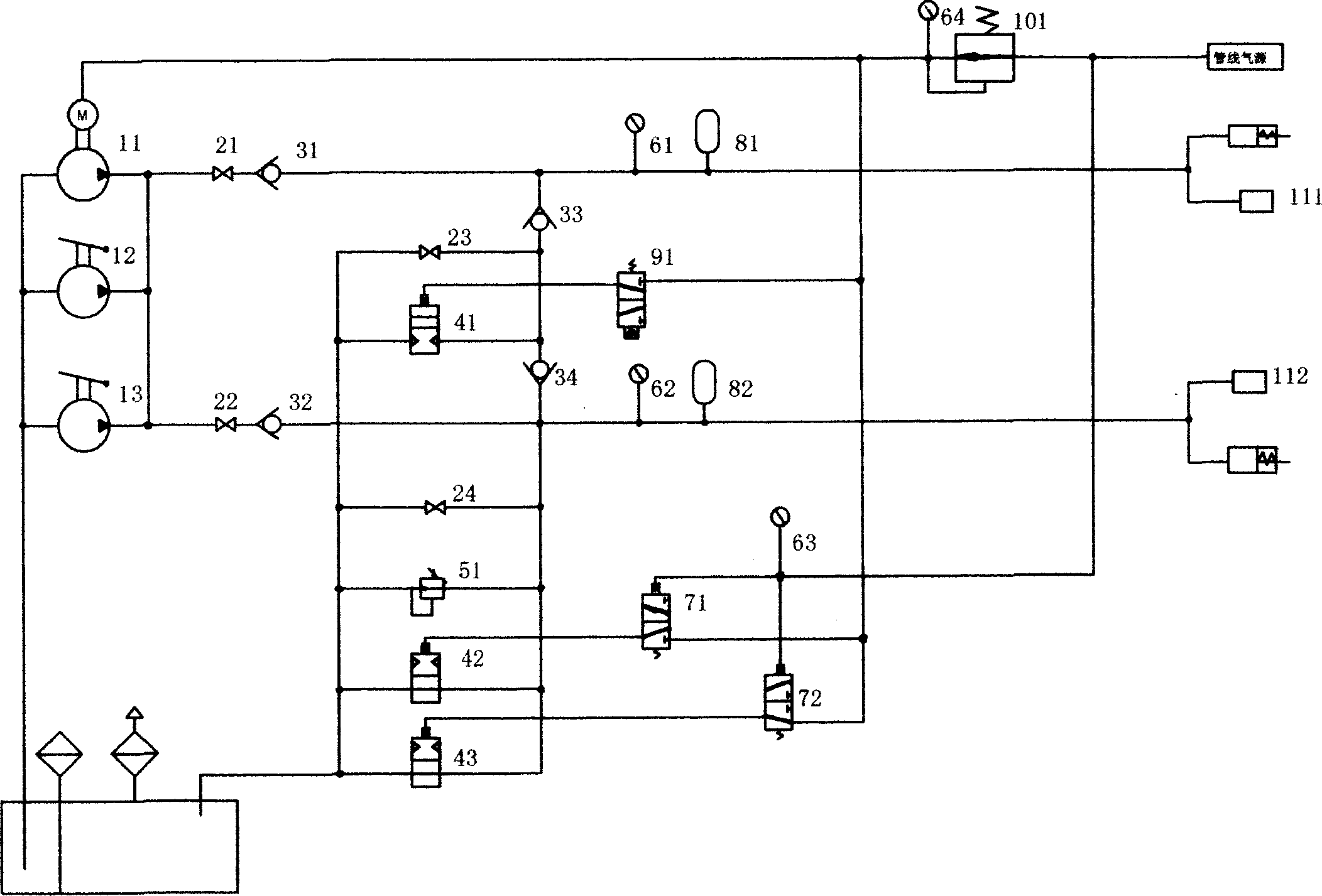
[0015] See figure 1 , A wellhead safety valve control system, including a high-pressure pump 11, manual pumps 12, 13, and a ground safety valve control circuit. The ground safety valve control circuit includes a stop valve 22, a one-way valve 32, a pressure gauge 62, and an accumulator 82. The four are connected in sequence, and an overflow valve 51 is set between the one-way valve 32 and the pressure gauge 62. One end of the stop valve 22 is connected to the high-pressure pump 11, and one end of the accumulator 82 is connected to a ground safety valve. The stop valve 22 is A high-pressure needle valve. The high-pressure pump 11 is a pneumatic booster pump and is connected to a pipeline air source. A high-pressure needle valve 24 is provided between the one-way valve 32 and the pressure gauge 62 in the ground safety valve control loop. A downhole safety...


PUM


Abstract

The invention relates to a well safety valve control system, which comprises: an air-powered pressurizing pump and a ground safety valve control circuit, wherein said ground safety valve control circuit comprises one high-pressure needle valve, one-way valve, a pressure meter, and an energy accumulator; one overflow valve is between the one-way valve and the pressure meter; one end of high-pressure needle valve is connected to the air-powered pressurizing pump; one end of energy accumulator is connected to the ground safety valve and connected to the air source; another high-pressure needle valve is between the one-way valve and the pressure meter; the under-well safety valve control circuit is between the air-powered pressurizing pump and the under-well safety valve; said circuit comprises one high-pressure needle valve, one-way valve, pressure meter, and energy accumulator which are connected; another branch is between the one-way valve and the pressure meter, whose another end is connected between the one-way valve and the pressure meter; said branch has two one-way valves; one high-pressure needle valve is between two one-way valves.

Description

Technical field [0001] The invention relates to a device for extracting oil or natural gas from a deep well, in particular to a wellhead safety valve control system for oil or natural gas. Background technique [0002] At present, the opening pressure of safety valves in most oil and gas wells in northwestern my country is about 15000psi (100MPa), while the traditional hydraulic devices used in existing systems can only reach 5000psi (35MPa), which cannot meet the requirements. Since the use site is an inflammable and explosive environment with a high concentration of natural gas, the explosion-proof level is required to be above EXD IIBT4, and the electric hydraulic pump and solenoid valve are used in the existing system, which will cause the system to heat up and easily generate electric sparks during operation. The existing technology can only control surface safety valves, but cannot control downhole safety valves. Oil and gas wells need to maintain the open state for a long ...

Claims


Application Information

Patent Timeline
Patent Type & Authority Applications(China)
IPC IPC(8): E21B33/03E21B34/02
Inventor 何建辉
Owner 深圳市弗赛特科技股份有限公司
Why Eureka
Try Eureka