Control device and method of buffer zone

A control method and technology of a control device, which are applied to instruments, electrical digital data processing, etc., can solve problems such as poor storage efficiency of a buffer zone 120, and achieve the effects of reducing idle space and improving storage efficiency.

Active Publication Date: 2008-10-15
VIA TECH INC
View PDF3 Cites 0 Cited by
  • Summary
  • Abstract
  • Description
  • Claims
  • Application Information

AI Technical Summary

Problems solved by technology

Therefore, the storage efficiency of the buffer 120 in the conventional architecture is poor

Method used


Image

  • Control device and method of buffer zone
  • Control device and method of buffer zone
  • Control device and method of buffer zone

Examples


Embodiment Construction

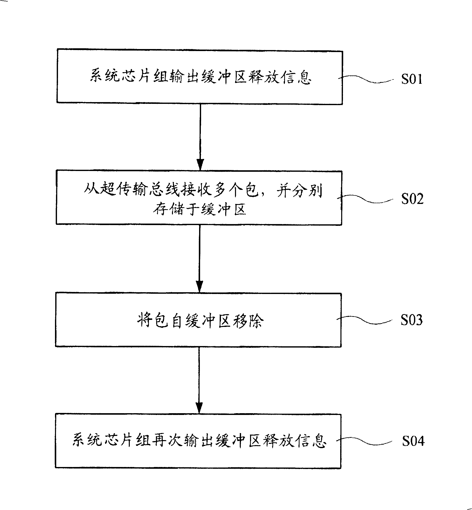
[0027] A buffer control method and a buffer control device for a packet bus according to preferred embodiments of the present invention will be described below with reference to related figures.

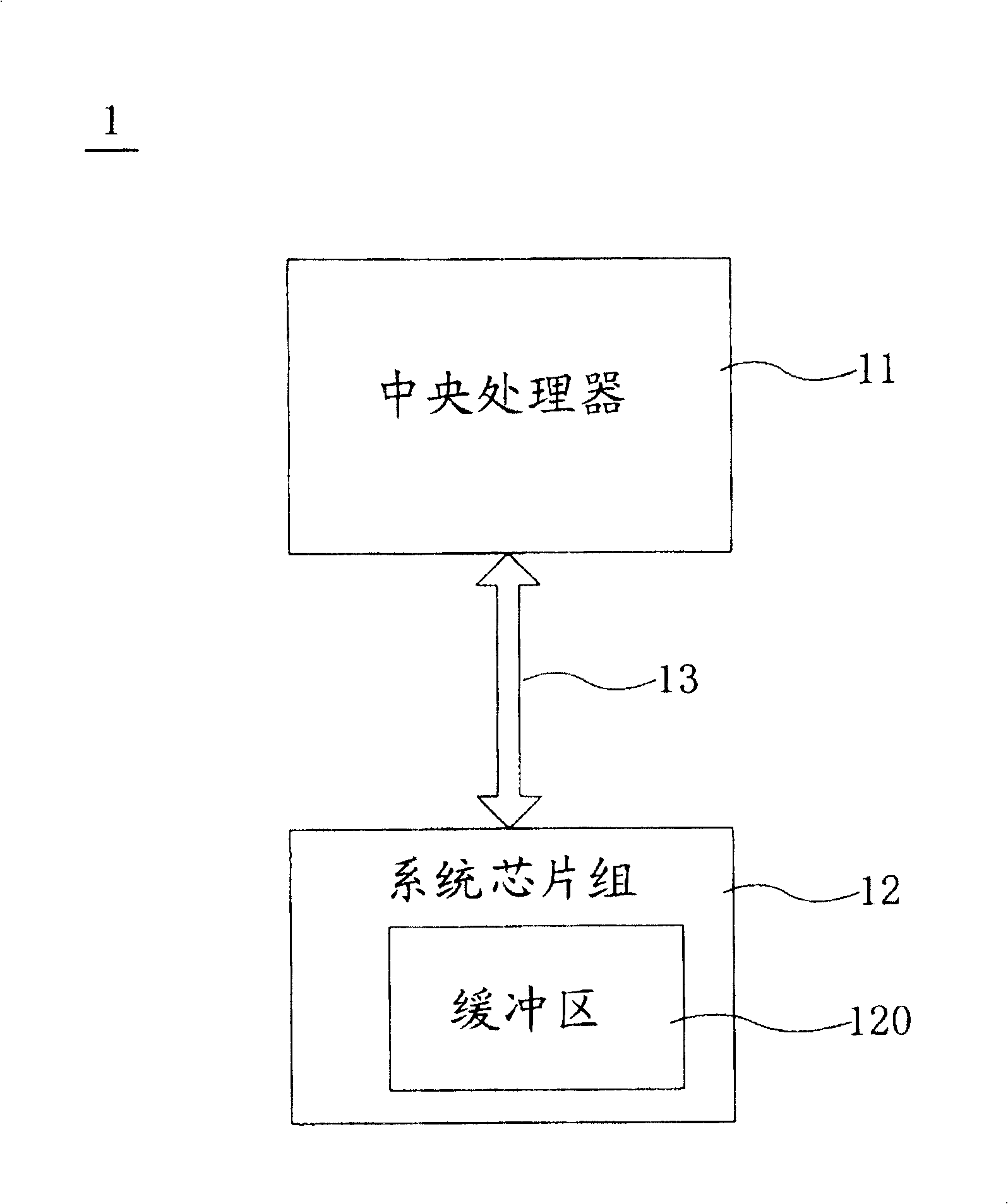
[0028] see Figure 4 and Figure 5 , the buffer control device (not labeled) according to the preferred embodiment of the present invention is placed in an integrated circuit 2, which includes a buffer 20 and a buffer controller 21. The integrated circuit 2 is electrically connected to another integrated circuit 4 through a packet bus 3 . The buffer 20 includes an instruction buffer 22 and a data buffer 23 . The buffer controller 21 includes a counter 211 and a comparator 212 .

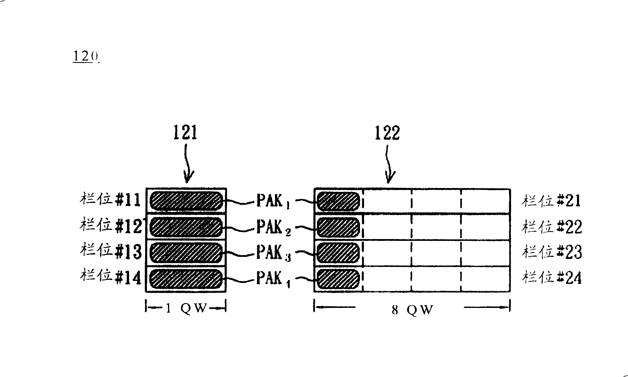
[0029]The integrated circuit 4 respectively transmits packets to the buffer 20 of the integrated circuit 2 through the packet bus 3 . The header of the packet will be stored in the command buffer 22 , and the data of the packet will be stored in the data buffer 23 . The counter 211 is used for counting ...


PUM


Abstract

The invention provides method and apparatus for buffer area which are used to control the pack storage of a buffer area, and the buffer area contains a data buffer area and a command store area. The method includes: calculating the number of the storage packages in the data buffer area; transmitting one of the many packages to the buffer area, the calculated value is refreshed according to the storing state of the buffer area, the calculated value denotes the remaining storage space; comparing the calculated value with the largest data package length to judge weather or not to increase the storage packages in the buffer area. The said controlling apparatus and method for buffer area can express the storing state in the data buffer area to reduce the idle space in the data buffer area, and improve the storage efficiency of the data buffer area.

Description

technical field [0001] The invention relates to a buffer control method and a buffer control device, in particular to a buffer control method and a buffer control device for a packet bus. Background technique [0002] As the processing speed and efficiency of the chips in the computer system are getting faster and faster, the transmission speed of the bus connecting each chip must also be increased, so that the performance of the computer system can be effectively improved. For the central processing unit in a computer system, its operating frequency has reached several GHz. In order to optimize the performance of the central processing unit, the front-side bus between the central processing unit and the system chipset must have a sufficiently high data transmission speed. So that the central processing unit has enough data to process and always keep in the state of operation. [0003] figure 1 It is a block diagram of the CPU 11 and the system chipset 12 in the known comp...

Claims


Application Information

Patent Timeline
Patent Type & Authority Patents(China)
IPC IPC(8): G06F13/42
Inventor 苏俊源谢易霖
Owner VIA TECH INC
Why Eureka
Try Eureka