Flexible element

A spring unit, vehicle technology, applied in the direction of vehicle springs, vehicle components, springs/shock absorbers, etc., can solve the problems of reducing the bearing surface area of ​​the end plate, space constraints, and difficult installation of bolts

Inactive Publication Date: 2008-10-22
VOLVO ARTICULATED HAULERS
View PDF8 Cites 0 Cited by
  • Summary
  • Abstract
  • Description
  • Claims
  • Application Information

AI Technical Summary

Problems solved by technology

[0003] A disadvantage of the above design of the connector is that the tension transmitted from the bolts by the spring unit is transferred through the end plate, the U-shaped joint unit and the ring joint unit, which means that the end plate has to be made relatively strong (thick) so that when When the fact that the tensile force increases the bending moment of the end plate occurs, the end plate will not be deformed
Another disadvantage is the relatively large space taken up by the fastening nuts for the U-shaped coupling unit, which reduces the bearing surface area of ​​the end plate against the frame or axle
Finally, the said 8 bolts are relatively difficult to install, especially in the field of service and repair, because the space available under the car is relatively limited and there are strict requirements that the bolts be tightened with the correct torque

Method used


Image

  • Flexible element
  • Flexible element
  • Flexible element

Examples


Embodiment Construction

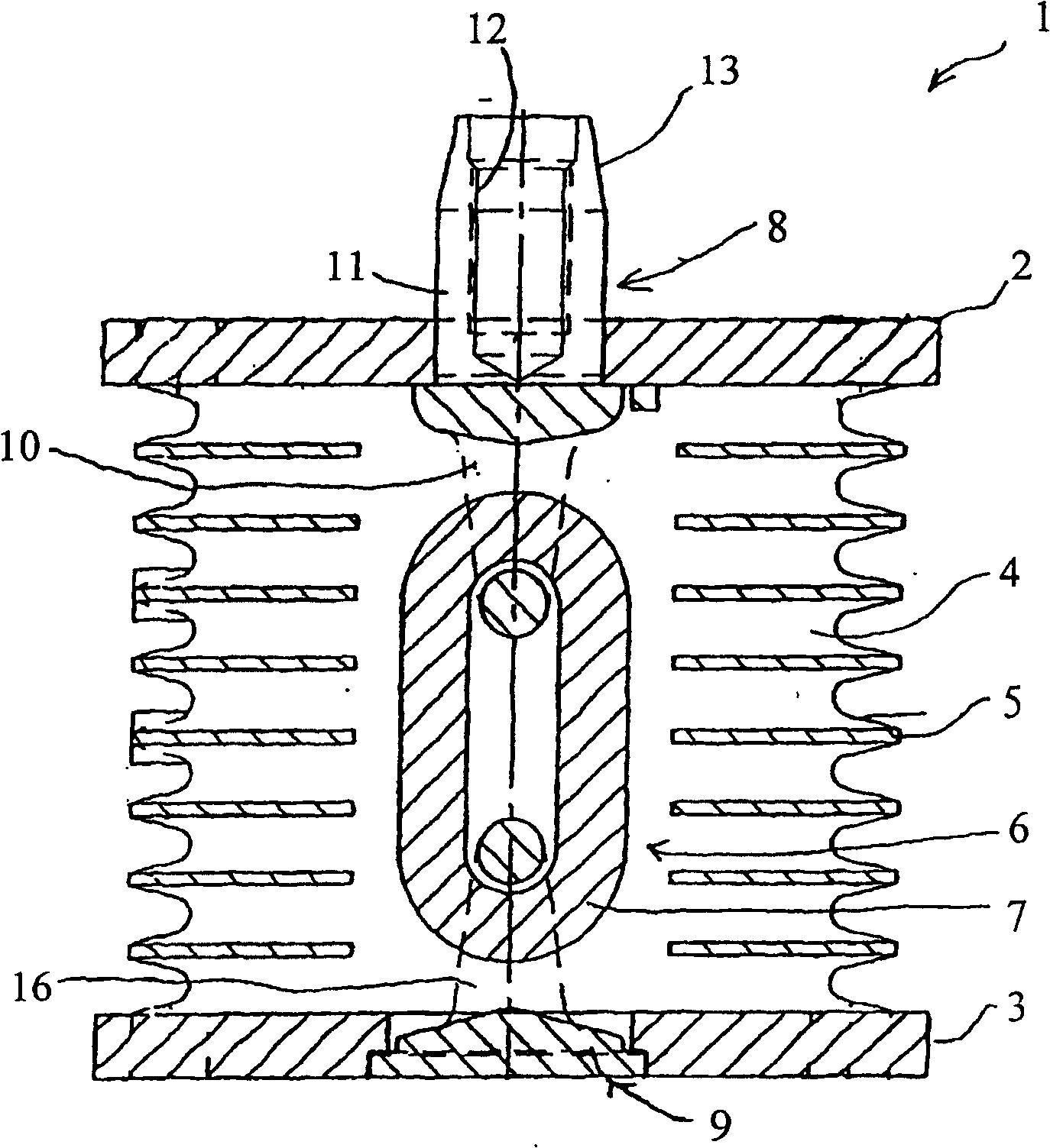
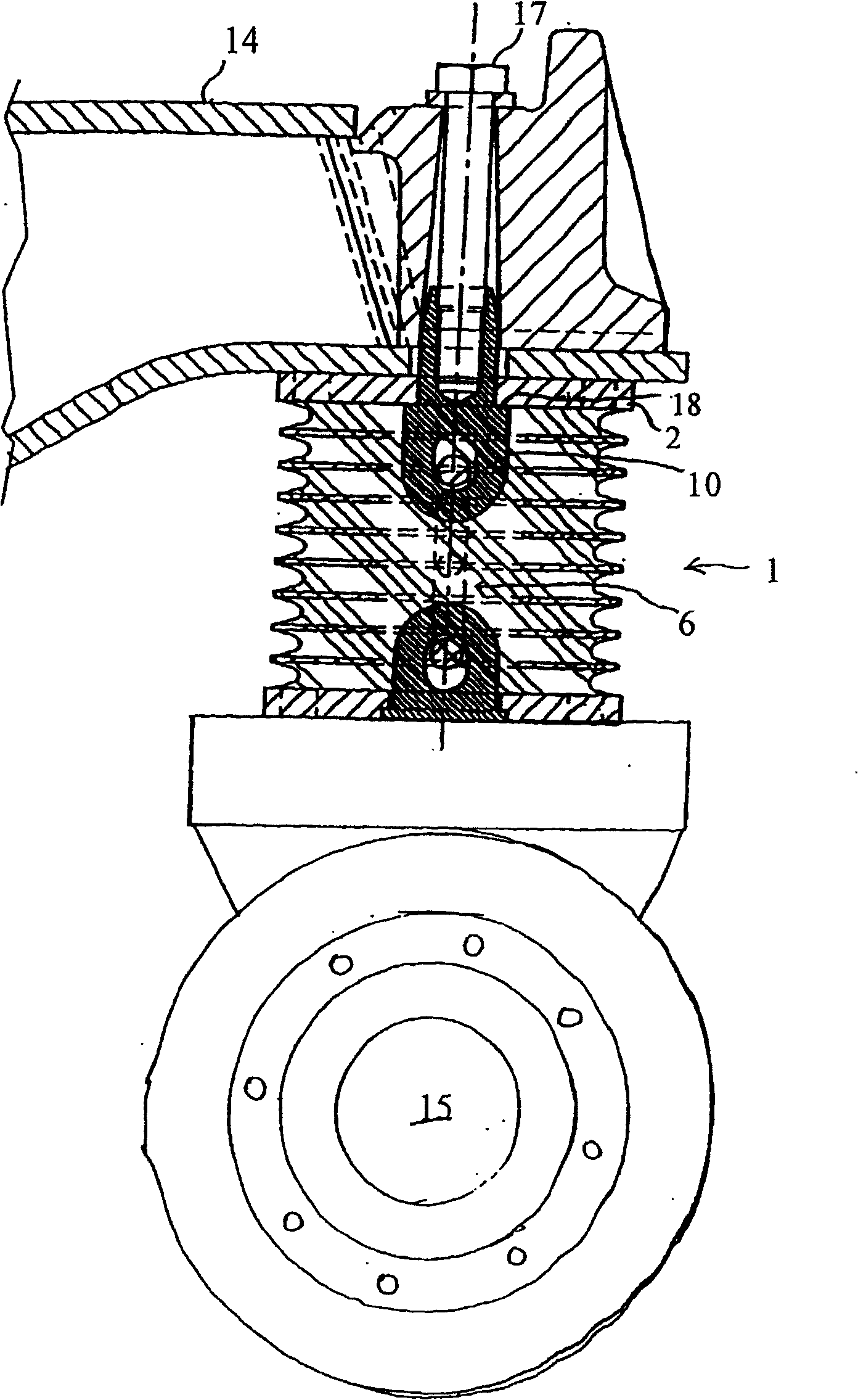
[0017] figure 1 A schematic diagram of a first embodiment of a spring unit 1 according to the invention is shown. The spring unit 1 comprises a first end plate 2 and a second end plate 3 which are substantially parallel when the spring unit 1 is empty. Between the end plates 2, 3 there is a vulcanized solid cylindrical rubber body 4, in a manner known per se, by using a plurality of parallel and separated flat metal rings 5 ​​to resist the outward movement of the rubber body 4 during compression Expand to strengthen the rubber body.

[0018] The end plates 2, 3 are held together by the use of a mechanical connection 6 comprising an endless chain connection 7 which connects the rubber body 4 protruding from the central part of the respective end plates 2, 3 into the rubber body 4. The first coupling mechanism 8 and the second coupling mechanism 9.

[0019] On the one hand, the first coupling mechanism 8 has a U-shaped connecting unit 10, which extends into the rubber body 4 ...


PUM


Abstract

The present invention relates to a spring element 1 intended to transmit compression forces and tensile forces between a vehicle frame 14 and a wheel axle 15 arranged movably in relation to the vehicle frame 14, especially between the wheel axle 15 and the end of a bogie beam mounted pivotably in the vehicle frame 14. The spring element 1 comprises a rubber body 4, and a mechanical connection member 6 which extends through the rubber body 4 and is arranged to limit the distancing movement between said vehicle frame 14 and wheel axle 15. The connection member 6 here comprises a coupling device 8 for coupling the connection member 6 in one of said vehicle frame 14 or wheel axle 15.

Description

technical field [0001] The present invention relates to a spring unit for transmitting compressive and tensile forces between a vehicle frame and an axle arranged to move relative to the vehicle frame, in particular between the wheel axle and the end of a bogie beam rotatably mounted in the vehicle frame force. The spring unit comprises a rubber body and a mechanical connection passing through the rubber body and arranged to limit the movement away between the frame and the axle. Background technique [0002] SE 436 480 B already discloses a spring unit for transmitting compressive and tensile forces between a vehicle frame and an axle arranged to move relative to the frame. The spring unit comprises two substantially parallel end plates and a connecting piece with a solid cylindrical rubber body between the two end plates, the connecting body limits the relative movement between the end plates. The connecting piece includes a U-shaped connecting body and an annular connec...

Claims


Application Information

Patent Timeline
Patent Type & Authority Patents(China)
IPC IPC(8): B60G11/22F16F1/40B60G5/02B60G7/00B60G11/24
CPCB60G2200/318B60G7/008B60G2204/45B60G2204/125B60G2202/141B60G2202/1422F16F1/40B60G5/02B60G11/24
Inventor 谢尔-奥弗·耶特霍坎·斯蒂格松
Owner VOLVO ARTICULATED HAULERS
Why Eureka
Try Eureka