Check patentability & draft patents in minutes with Patsnap Eureka AI!

Ball screw device

A technology of ball screw and ball, which is applied in the direction of transmission, gear vibration/noise attenuation, belt/chain/gear, etc. It can solve the problems of low acoustic performance and large clearance, achieve good acoustic performance, and suppress ball competition. Squeeze, the effect of improving mobility

Inactive Publication Date: 2008-10-22
NSK LTD +1
View PDF5 Cites 4 Cited by
  • Summary
  • Abstract
  • Description
  • Claims
  • Application Information

AI Technical Summary

Problems solved by technology

[0006] In such a ball screw device, it is easier to suppress the occurrence of noise, vibration, etc., compared with the use of a ball circulation tube. However, if the ratio of the diameter of the ball return passage to the ball diameter is too large, the ball return passage will be damaged. The clearance of the ball (the amount of clearance between the ball return through passage and the ball) becomes larger
Therefore, the arrangement of the balls in the ball return passage tends to meander, and the balls in the ball return passage advance while colliding with the inner surface of the ball return passage when the screw shaft or the nut rotates at high speed, resulting in poor acoustic performance. question

Method used


Image

  • Ball screw device
  • Ball screw device
  • Ball screw device

Examples


Embodiment Construction

[0019] Embodiments of the present invention will be described below with reference to the drawings.

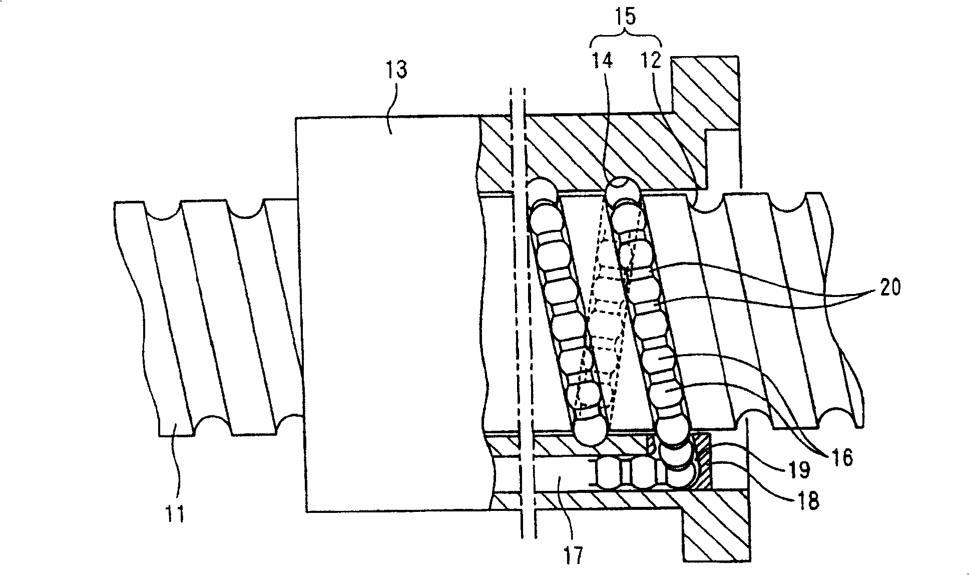
[0020] figure 1 It is a sectional view of the ball screw device according to the first embodiment of the present invention. In this figure, reference numeral 11 is a screw shaft of the ball screw device according to the first embodiment of the present invention, and a ball screw groove 12 is formed on the outer diameter surface of the screw shaft 11 . In addition, reference numeral 13 is a nut having a ball screw groove 14 opposite to the ball screw groove 12 of the screw shaft 11 on the inner diameter surface, and the ball screw groove 14 of the nut 13 and the ball screw of the screw shaft 11 A plurality of balls 16 are provided between the screw grooves 12 , and they roll in a helical ball-loaded rolling path 15 formed between the ball screw grooves 12 and 14 as the screw shaft 11 or the nut 13 rotates.

[0021] The nut 13 is formed along the axial direction of the screw s...


PUM


Abstract

A ball screw device capable of providing excellent acoustic performance even when a screw shaft or a nut is rotated at a high speed. Where the diameter of a ball 16 is Dw and the diameter of a ball returning through passage 17 formed in the nut 13 is D1, the ball returning through passage 17 is formed in the nut 13 so that the requirement of (D1- Dw) <= 0.1 Dw is satisfied. Also, where the diameter of the ball 16 is Dw and the diameter of a ball rolling passage 19 formed in a ball rolling member 18 is D2, the ball rolling passage 19 is formed in the ball rolling member 18 so that the requirement of (D2 - D2) <= 0.1 Dw can be satisfied.

Description

technical field [0001] The present invention relates to an improvement as a ball screw device for converting rotary motion into linear motion. Background technique [0002] A ball screw device used in a conveyance mechanism of a machine tool, etc. includes a screw shaft, a nut having a ball screw groove on an inner diameter surface opposite to a ball screw groove formed on an outer diameter surface of the screw shaft, and the nut and the above-mentioned nut. A plurality of balls that roll along the ball-loaded rolling path formed between the ball screw grooves of the screw shaft as the screw shaft or nut rotates. [0003] The nut of such a ball screw device, for example, moves relatively linearly in the axial direction of the screw shaft as the balls roll in the ball-loaded rolling path as the screw shaft rotates. However, in order to continue the relative linear motion of the nut, it is necessary to The balls rolling in the ball load rolling path repeatedly roll in the bal...

Claims


Application Information

Patent Timeline
Patent Type & Authority Patents(China)
IPC IPC(8): F16H25/22
CPCF16H25/2219F16H25/2238F16H57/0006Y10T74/19777
Inventor 加藤将人
Owner NSK LTD
Features
  • R&D
  • Intellectual Property
  • Life Sciences
  • Materials
  • Tech Scout
  • Unparalleled Data Quality
  • Higher Quality Content
  • 60% Fewer Hallucinations
Learn More