Method for detaching a semiconductor chip from a foil and apparatus for mounting semiconductor chips

A technology of semiconductors and chips, which is applied in the field of equipment for installing semiconductor chips, and can solve problems such as destroying semiconductor chips

Inactive Publication Date: 2008-10-22
OERLIKON ASSEMBLY EQUIP STEINHAUSEN
View PDF6 Cites 1 Cited by
  • Summary
  • Abstract
  • Description
  • Claims
  • Application Information

AI Technical Summary

Problems solved by technology

The disadvantage of these methods is that adjacent semiconductor chips are destroyed since the edge height required for separation must be around 1.5 mm

Method used


Image

  • Method for detaching a semiconductor chip from a foil and apparatus for mounting semiconductor chips
  • Method for detaching a semiconductor chip from a foil and apparatus for mounting semiconductor chips
  • Method for detaching a semiconductor chip from a foil and apparatus for mounting semiconductor chips

Examples


Embodiment Construction

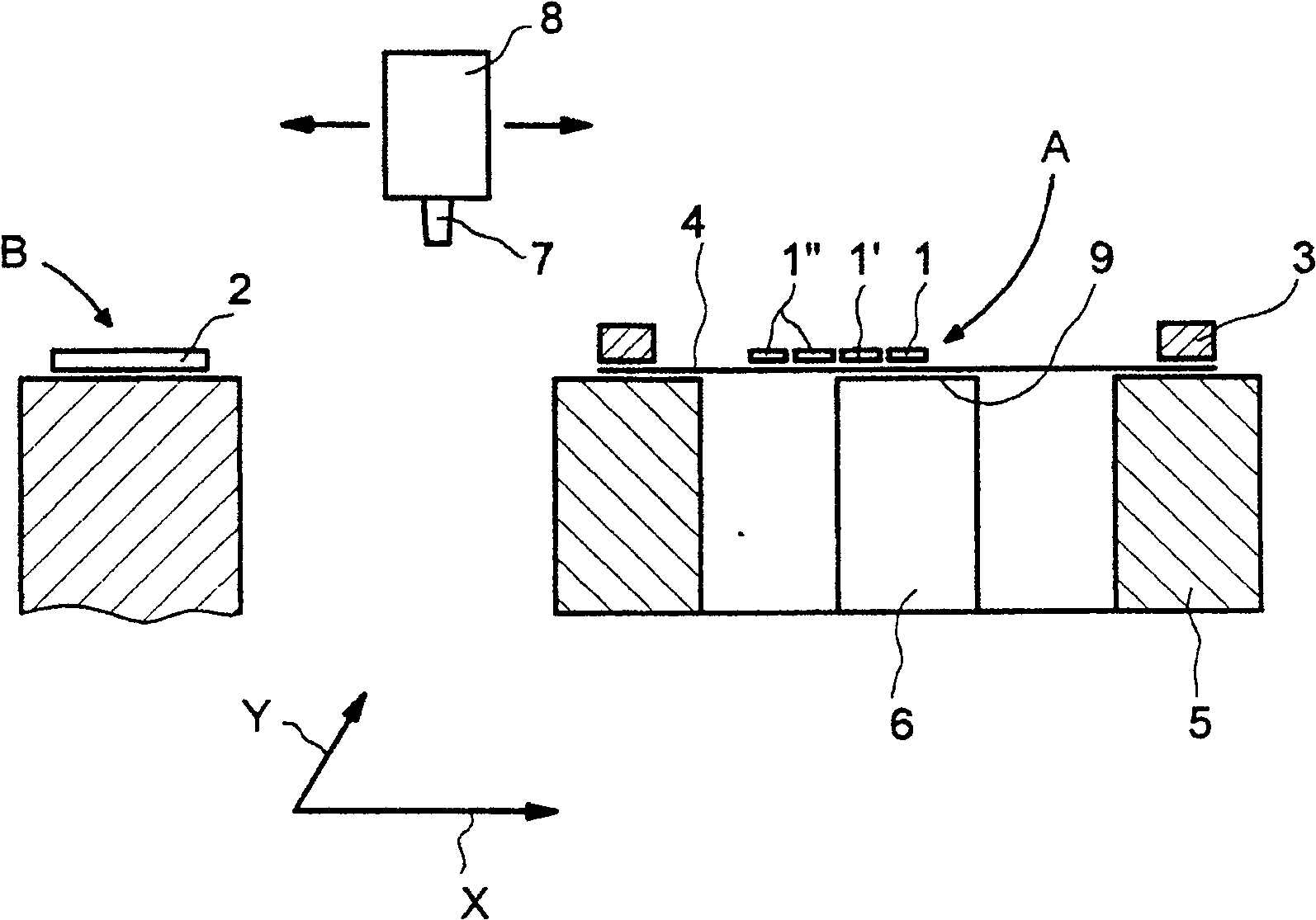
[0046] figure 1 A simplified schematic diagram of a device for mounting semiconductor chips 1 , 1 ′, 1 ″ on a substrate 2 is shown. The semiconductor chips 1 , 1 ′, 1 ″ arranged in rows and columns are attached to, for example, held in frame 3 on the foil 4. The apparatus has a accommodating frame 3 and a movable wafer stage 5 that provides the semiconductor chips 1 in a first position A one after the other. In the first position A, the chip ejector 6 according to the invention is arranged under the foil 4 , which in this example is an ejector without ejector pins. The chip ejector 6 serves to support the separation of the semiconductor chip 1 from the foil 4 when the semiconductor chip 1 is removed. The wafer stage 5 can move in two vertical directions, x and y. The foil 4 is arranged so that the edges of the semiconductor chips 1, 1', 1" are almost parallel to the directions x and y. The device also has a chip gripper 7 for transferring the semiconductor chips 1 provided ...


PUM


Abstract

Under the support of a chip ejector (6), a semiconductor chip (1) is separated from a foil (4), and the semiconductor chip (1) is picked up from the foil (4). The chip ejector (6) is provided with an incline (16) and a support area (13) which is provided with a groove (12) arranged close to a stripping edge (18). A surface (17) of the incline (16) is a concave and is stopped at the stripping edge (18) which is protrudent from the surface (9) of the chip ejector (6). The groove (12) can be vacuumized. The separation and picking-up of the semiconductor chip (1) and the foil (4) are generated by the relative movement of a wafer platform (5) towards the chip ejector (6), so as to be convenient for the stripping edge (18) protruding from the surface (9) of the chip ejector to pull the foil (4), accordingly the semiconductor chip (1) is at least partially separated from the foil (4) temporarily by self and lands at the foil (4) above the support area (13), and a chip gripper (7) picks up the semiconductor chip (1) placed at the support area (13).

Description

technical field [0001] The present invention relates to a method for separating a semiconductor chip from a foil and an apparatus for mounting a semiconductor chip, the apparatus being suitable for carrying out the method. Background technique [0002] Typically, semiconductor chips are provided on foils held in frames known in the industry as tapes for handling using such a mounting apparatus. The semiconductor chip is adhered to the foil. The frame with foil is accommodated by a movable wafer stage. The wafer stage is moved cyclically so that the semiconductor chips are provided one after the other in the first position A, and then the provided semiconductor chips are picked up by the chip gripper and placed in the second position B on the substrate. Removal of the provided semiconductor chip from the foil is supported by a chip ejector (known in the art as a die ejector) disposed under the foil. In this way, at least one ejector pin, usually provided in the chip ejecto...

Claims


Application Information

Patent Timeline
Patent Type & Authority Patents(China)
IPC IPC(8): H01L21/00H01L21/68
Inventor 乔纳森·梅丁马丁纳·勒斯滕伯格马赛尔·尼德豪泽丹尼尔·施内茨勒罗兰德·斯塔尔德
Owner OERLIKON ASSEMBLY EQUIP STEINHAUSEN
Why Eureka
Try Eureka