Energy-saving type parallel connection vacuum generator

A vacuum generator, energy-saving technology, applied in the direction of machines/engines, non-displacement pumps, mechanical equipment, etc., can solve the problems of fast production and energy saving, reduce the weight of the whole machine, and meet the response speed , the effect of saving energy

Inactive Publication Date: 2008-11-05
ZHEJIANG UNIV OF TECH
View PDF5 Cites 0 Cited by
  • Summary
  • Abstract
  • Description
  • Claims
  • Application Information

AI Technical Summary

Problems solved by technology

[0003] In order to overcome the problem that the vacuum generator in the prior art can only meet a certain exhaust volume and vacuum degree, and cannot solve the contradiction between fast production and energy saving, the present invention provides a vacuum generator that can meet different exhaust volumes and vacuum degrees. , energy-saving parallel vacuum generators with fast response and energy saving

Method used


Image

  • Energy-saving type parallel connection vacuum generator

Examples


Embodiment 1

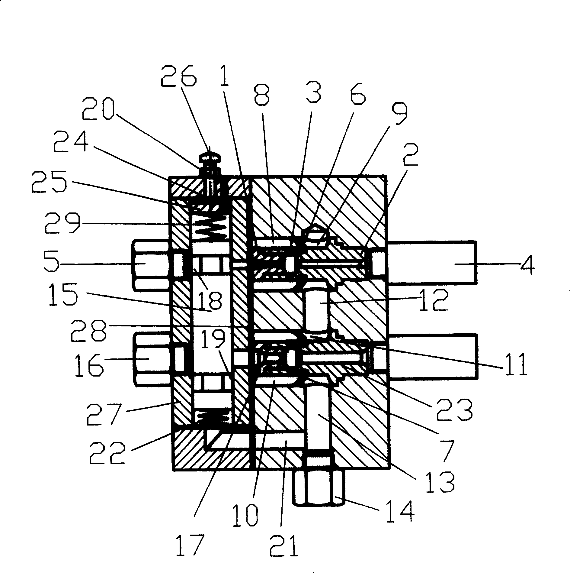
[0017] Energy-saving parallel vacuum generator, which includes parallel first vacuum generator assembly and second vacuum generator assembly, each vacuum generator assembly includes compressed gas connection, nozzle, expansion tube, vacuum chamber and muffler , taking the first vacuum generator assembly as an example: there is a first nozzle 1 and a first expansion tube 2 in the cavity of the machine body, the first nozzle 1 and the first expansion tube 2 are in sealing connection, the first nozzle 1 The pipeline of the pipeline and the first expansion tube 2 constitutes the first air flow channel, the first nozzle 1, the first expansion tube 2 and the inner wall of the body enclose the first vacuum chamber, and the first air flow channel passes through the first suction hole 3 and the The first vacuum chamber is connected, the end of the first expansion tube 2 is connected to the first muffler 4, the first compressed gas joint 5, the first nozzle 1, the first expansion tube 2 ...

Embodiment 2

[0024] refer to figure 1A backing plate 25 with a longitudinal through hole 24 is fixedly connected in the valve chamber, the backing plate 25 is connected with the adjusting screw 26, and the backing plate 25 is located between the valve lower cover plate and the valve core 15 , the adjusting screw 26 extends out of the valve body, and the backing plate is connected with the valve core through an adjusting spring 29 . The preload of the spring can be adjusted by adjusting the adjusting screw 26 . The rest of the structure and implementation are the same as in Embodiment 1.

Embodiment 3

[0026] refer to figure 1 , there is a sealing ring 28 between the valve body and the body. After the sealing ring 28 is set, it can be ensured that the vacuum generator can work normally. The rest of the structure and implementation are the same as in Embodiment 1.


PUM


Abstract

The invention relates to an energy conservation parallel connection vacuum generator that includes two vacuum generators connecting in parallel. The nozzle and caliber of one generator is bigger than that of the other. The vacuum chamber of each generator is separated to front vacuum room and back vacuum room by one-way valve, and the back vacuum rooms are connected by connecting hole. And including a switching valve to make the vacuum generator starting correspond to the big air capacity vacuum generator, and the continuously working stage correspond to the small air capacity vacuum generator. The invention would satisfy the different responding speed, and conserve energy.

Description

technical field [0001] The invention relates to a vacuum generator. Background technique [0002] At present, with the continuous improvement of the level of industrial automation, vacuum generators and vacuum suction cups have been widely used in automatic manufacturing production lines, assembly automatic lines, warehouse management and robots in the automobile manufacturing industry, household appliance manufacturing industry, glass manufacturing industry, plastic parts manufacturing industry and other industries. It has been widely used, such as washing machine assembly automatic line, stamping automatic line, automobile assembly automatic line and other automatic lines, a large number of vacuum generators and vacuum suction cups are used. Since automatic lines and robots require short beats and fast response speeds during work, the vacuum suction cups are required to generate vacuum as fast as possible. In order to achieve this purpose, the volume of the vacuum suction...

Claims


Application Information

Patent Timeline
Patent Type & Authority Patents(China)
IPC IPC(8): F04F5/54F04F5/52
Inventor 郑欣荣计时鸣张宪朱晟佺薛伟
Owner ZHEJIANG UNIV OF TECH
Why Eureka
Try Eureka