Front set absorber for motorcycle

A technology for front shock absorbers and motorcycles, applied in axle suspension devices, bicycle accessories, transportation and packaging, etc., can solve problems such as front fork tube 2 empty travel phenomenon, impact on shock absorption effect, liquid flow interference, etc., and achieve effective Conducive to popularization and application, improving shock absorption effect and improving comfort

Inactive Publication Date: 2008-11-12
CHONGQING YUAN INNOVATION TECH GROUP
View PDF6 Cites 0 Cited by
  • Summary
  • Abstract
  • Description
  • Claims
  • Application Information

AI Technical Summary

Problems solved by technology

Since the main liquid flow direction is from chamber III13 to chamber I11 through the inner hole of piston tube 3, the oil in chamber II12 can only be sucked into the chamber by the negative pressure formed when the front fork pipe 2 moves downward relative to the base cylinder 1 Because there is a vacuum in the chamber III13, there will inevitably be insufficient oil suction in the chamber II12 to generate a vacuum phenomenon. Such a result will cause the front fork tube 2 to appear empty stroke phenomenon when the compression movement suddenly changes to the recovery movement (no damping force or damping force is very small, the higher the speed, the more obvious this situation), which affects the shock absorption effect and reduces the comfort and safety of riding
[0004] In order to solve a series of problems caused by the above-mentioned liquid flow interference, those skilled in the art have carried out continuous exploration and repeated experiments, including setting the damping hole obliquely. The role played is very limited, and the practicability is not great; at the same time, because the adverse effects brought by the damping hole have not been noticed by people for a long time, naturally no one has studied this, let alone the appearance of a solution, so up to now An ideal solution has not been found so far

Method used


Image

  • Front set absorber for motorcycle
  • Front set absorber for motorcycle
  • Front set absorber for motorcycle

Examples


Embodiment Construction

[0013] The present invention will be further described below in conjunction with accompanying drawing.

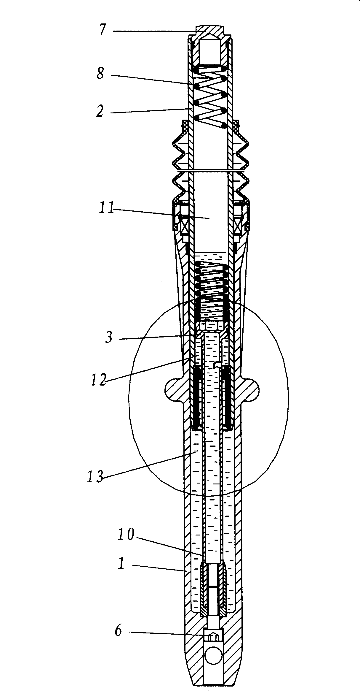
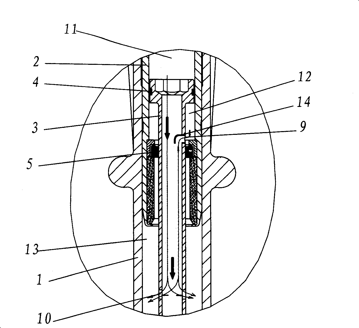
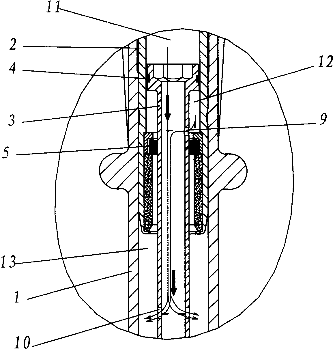
[0014] Such as figure 1 with figure 2 As shown, the present invention includes a bottom tube 1, a front fork tube 2 and a piston tube 3, the lower end of the front fork tube 2 is located in the upper end of the bottom tube 1, and the outer wall of the front fork tube 2 is slidingly fitted with the bottom tube 1 inner wall. The upper end of the piston tube 3 is located in the lower end of the front fork tube 2, and a sealing ring 4 is arranged between the two, and the sealing ring 4 is located in an annular groove on the outer wall of the piston tube 3. The outer diameter of the upper end of the piston tube 3 is larger than that of the remaining parts, thereby forming a ladder. A one-way flow valve 5 is arranged between the outer wall of the smaller outer diameter part of the piston tube 3 and the inner wall of the front fork tube 2, and passes through the one-way flow va...


PUM


Abstract

The right front set buffer of motorcycle comprises the bottom barrel, front fork tube and piston tube to form cavity I, II and III, with damping holes on the piston tube to connect the cavity I and II, with flow guide valve inside the damp to stick into the cavity I and facing downward. It can greatly improve the buffer effect, comfort, stability and safety.

Description

technical field [0001] The invention relates to a motorcycle shock absorber, in particular to a motorcycle upright front shock absorber. Background technique [0002] The purpose of motorcycle shock absorbers is to slow down the impact of sports and improve riding comfort and safety. At present, the usual motorcycle front shock absorber structure is as follows: image 3 As shown, it includes a base cylinder 1, a front fork tube 2 and a piston tube 3, and the three form a chamber I11, a chamber II12 and a chamber III13 with each other. The basic principle of the formation of the damping force of the shock absorber is: when the front fork tube 2 moves upward relative to the base cylinder 1 (recovery movement), the oil flows from the chamber I11 and the chamber II12 to the chamber III13 through the flow hole 10, and the oil in the chamber II12 The liquid flows to the chamber I11 through the damping hole 9 on the piston tube 3 and the oil in the chamber I11 flows together to th...

Claims


Application Information

Patent Timeline
Patent Type & Authority Patents(China)
IPC IPC(8): B62K25/04
Inventor 张兴海李植
Owner CHONGQING YUAN INNOVATION TECH GROUP
Why Eureka
Try Eureka