
Main shaft structure for high-precision machine tool

A high-precision, spindle technology, applied to the parts of grinding machine tools, metal processing machinery parts, large fixed members, etc., can solve the problems of reduced service life of the spindle, low precision, inconvenient disassembly, etc., to increase rigidity and load bearing Power, improve the life of the spindle, fast and convenient assembly

Inactive Publication Date: 2015-12-16
WUXI SANLI BEARINGS
View PDF8 Cites 4 Cited by
  • Summary
  • Abstract
  • Description
  • Claims
  • Application Information

AI Technical Summary

Problems solved by technology

[0002] At present, the existing spindle structure used for high-precision machine tools generally has the problem of low precision. The precision of the spindle of a high-precision grinding machine with a diameter of about 170mm should be 0.005-0.010mm, while the precision of the spindle of a high-precision lathe with a diameter of about 170mm It should be above 0.020mm, but the precision of existing machine tool spindles cannot meet the above requirements
In addition, due to the unreasonable selection of bearings in the existing machine tool spindles, the rigidity of the spindles is poor. At the same time, the existing spindles are sealed with felt. This sealing method is not suitable for long-term use. It is very easy for coolant to enter the spindle structure, resulting in damage to the bearings inside the spindle structure. , which greatly reduces the service life of the main shaft, and the original spring seal ring wears on the main shaft and is prone to heat problems due to the increase of operating torque
Finally, when the existing main shaft structure is assembled, it is impossible to find whether the bearing is installed well or not in time. The quality of the bearing installation can only be determined after the main shaft structure is completely installed, and it is inconvenient to disassemble.

Method used


Image

  • Main shaft structure for high-precision machine tool

Examples


Embodiment Construction

[0021] The specific implementation manner of the present invention will be described below in conjunction with the accompanying drawings.

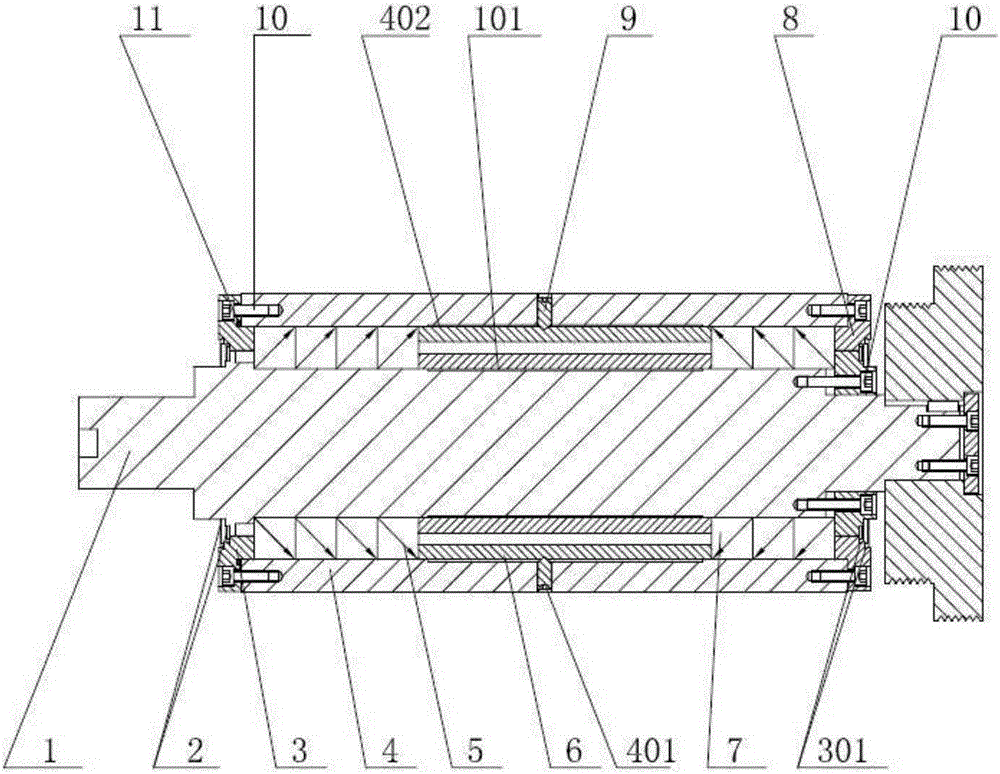
[0022] Such as figure 1 As shown, a spindle structure for a high-precision machine tool includes a shell 4 with a cavity, the shell 4 is a circular shell, the spindle 1 is installed inside the cavity of the shell 4, and the A plurality of first bearings 5 ​​and second bearings 7 are respectively connected in the cavity and on the outer periphery of the main shaft 1, the first bearings 5 ​​are angular contact ball bearings, the second bearings 7 are angular contact bearings, and the first bearings 5 ​​are offset against each other. Connected to be installed on the main shaft 1, each second bearing 7 is also mutually abutting and installed on the main shaft 1, the first bearing 5 is 4 among the present invention, and the second bearing 7 is 3 (the first bearing 5 and the second bearing The number of 7 is adjusted according to the actual pro...


PUM


Abstract

The invention relates to and provides a main shaft structure for a high-precision machine tool. The main shaft structure comprises a shell with a cavity. A main shaft penetrates the cavity of the shell. A plurality of first bearings and a plurality of second bearings are further connected in the cavity of the shell and connected to the periphery of the main shaft. The periphery of the part, between the first bearing on the innermost side and the second bearing, of the main shaft is sleeved with a space ring in a connected manner. The two ends of the shell are fixedly connected with end covers respectively. sealing rings are further arranged in step grooves in inner rings of the end covers. The part between the inner ring of at least one end cover and the periphery of the main shaft is further provided with a bearing locking adjusting piece. The bearing locking adjusting pieces are fixedly connected with the main shaft through fasteners. The main shaft structure has the beneficial effects of being high in precision and long in service life. Using of a high-precision lathe, a grinding machine and a numerical control machine tool can be effectively achieved, precision and rigidity are good, and good waterproof performance is achieved.

Description

technical field [0001] The invention relates to machine tool equipment, in particular to a spindle structure used for high-precision lathes, grinders and numerically controlled machine tools and other high-precision machine tools. Background technique [0002] At present, the existing spindle structure used for high-precision machine tools generally has the problem of low precision. The precision of the spindle of a high-precision grinding machine with a diameter of about 170mm should be 0.005-0.010mm, while the precision of the spindle of a high-precision lathe with a diameter of about 170mm It should be above 0.020mm, but the precision of the existing machine tool spindles cannot meet the above requirements. In addition, due to the unreasonable selection of bearings in the existing machine tool spindles, the rigidity of the spindles is poor. At the same time, the existing spindles are sealed with felt. This sealing method is not suitable for long-term use. It is very easy ...

Claims


Application Information

Patent Timeline
IPC IPC(8): B23B19/02B24B41/04
CPCB23Q1/70B24B41/04
Inventor 杨立印
Owner WUXI SANLI BEARINGS
Learn More