
Photoelectric speed monitoring method and device for train with magnetic transmission

A speed monitoring and magnetic transmission technology, applied in the direction of using optical devices to transmit sensing components, etc., can solve the problems of difficult impact inertia, pollution, mechanical failure of sensors, etc., and achieve the effect of solving mechanical failures and avoiding serious pollution of light sources.

Active Publication Date: 2008-11-26
株洲天利铁路机车车辆配件有限公司
View PDF6 Cites 0 Cited by
  • Summary
  • Abstract
  • Description
  • Claims
  • Application Information

AI Technical Summary

Problems solved by technology

In short, the use of this universal joint transmission mechanism will inevitably lead to mechanical failure or even damage to the sensor (the sensor cannot bear the impact inertia of the wheel set)
[0007] 2. The light source is seriously polluted
[0008] This type of photoelectric sensor uses a light source to turn intermittent light through a grating disc that rotates with the wheel shaft. Because it is a universal joint, this transmission mechanism directly communicates with the inner cavity of the wheel axle box, and cannot achieve a fully sealed state structurally. , the pollution of the grating disk will distort the optical signal and cause mutual pollution
First of all, the 0.2mm optical groove is very easy to be polluted, and secondly, the grating disc is also easily polluted
[0009] 3. The output waveform is highly distorted
Due to the processing accuracy of the grating disk and the rotating shaft, the square wave pulse is distorted, so the potentiometer or variable resistor is used for adjustment in the amplification and shaping circuit, and its accuracy is difficult to guarantee.
[0011] 4. Poor function scalability
[0012] One is that it is difficult to meet the requirements of train speed increase by using universal linkage mechanism. This structure itself is easy to cause mechanical failure. When the maximum speed is 1000r / min, the train speed is 198-235km / h. When the train speed reaches about 300km / h, The speed of the sensor is 1300~1500r / min. At this time, the requirements for the transmission mechanism are higher, and this kind of sensor is difficult to meet the requirements.

Method used

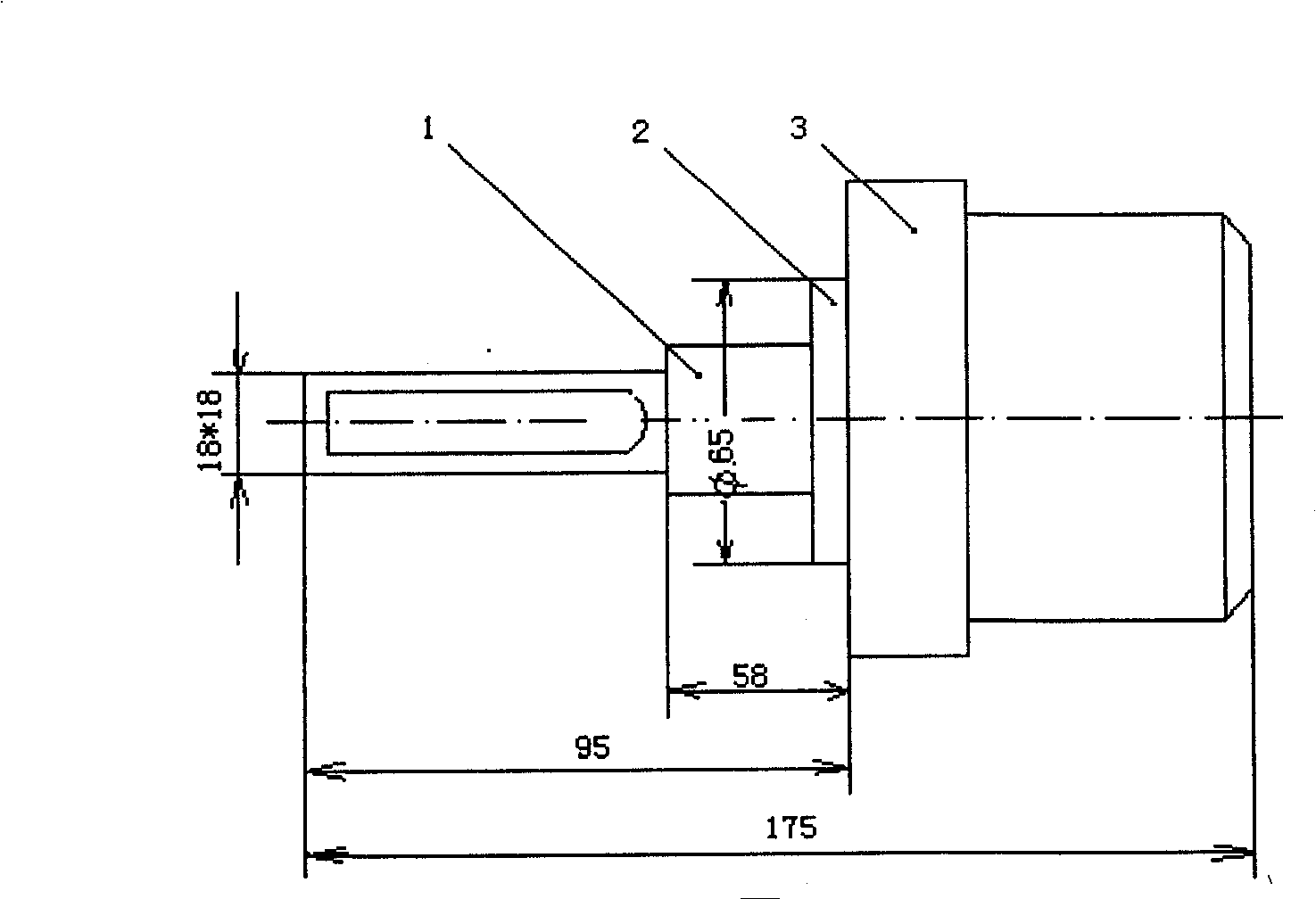
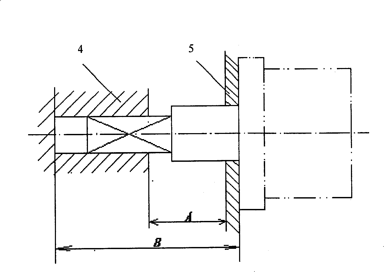

Image

  • Photoelectric speed monitoring method and device for train with magnetic transmission
  • Photoelectric speed monitoring method and device for train with magnetic transmission
  • Photoelectric speed monitoring method and device for train with magnetic transmission

Examples


Embodiment approach 1

[0031] Using magnetic coupling

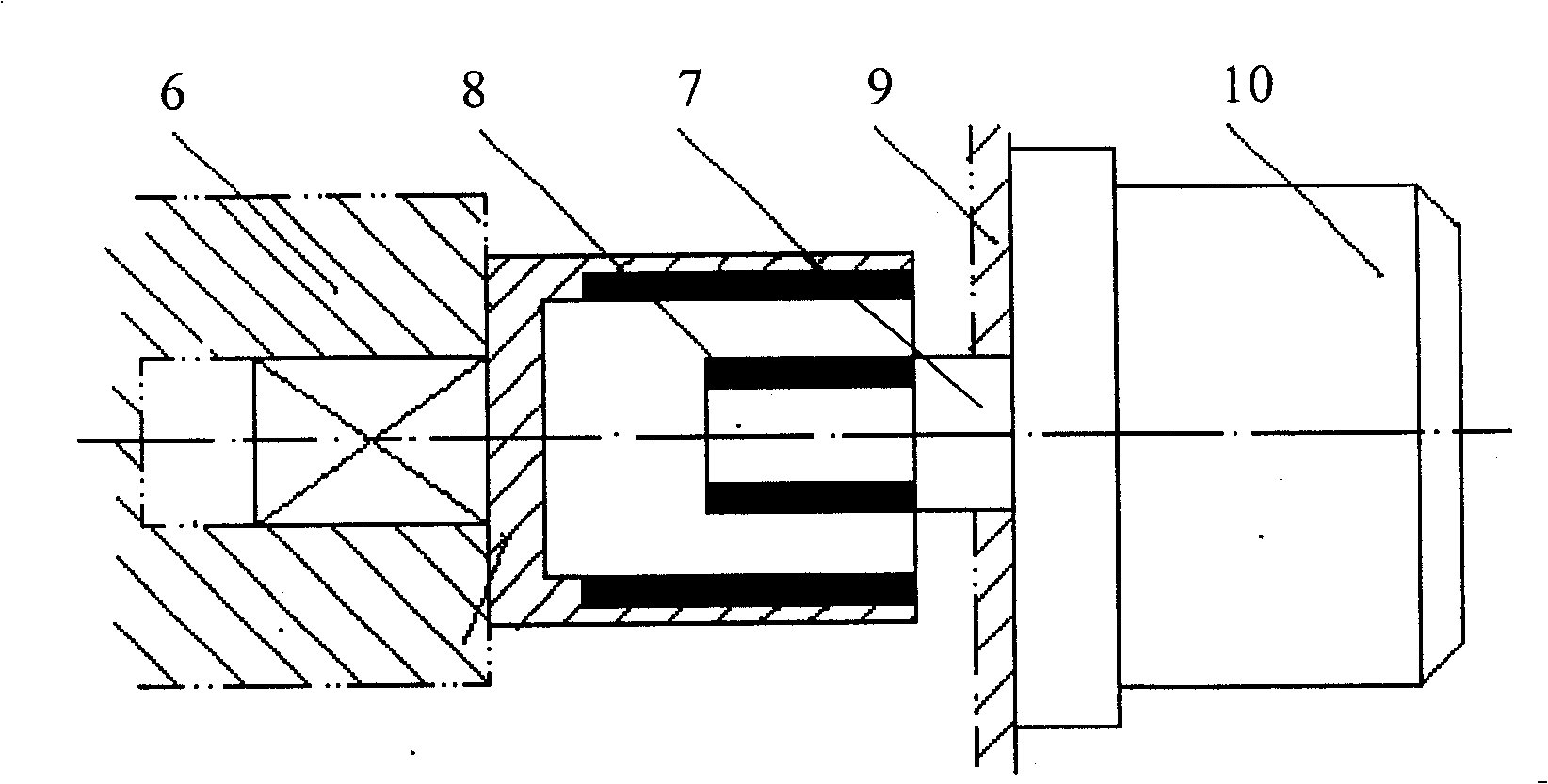
[0032] Use a new type of permanent magnet material (neodymium iron stilt) to form a magnetic coupler according to the number of pole pairs of 4, 6, 8, 12, 16..., such as image 3 shown. The large-end magnetic sleeve is installed on the wheel set, and the small-end magnetic force shaft is connected with the sensor shaft. When the wheel rotates, the sensor shaft is driven to rotate synchronously under the action of the magnetic torque. Main technical conditions The non-concentricity between the wheel shaft and the sensor shaft is ≤6mm, and the free lateral movement of the wheel shaft is >30mm.

Embodiment approach 2

[0034] Using magnetic drive

[0035] Use permanent magnet materials (NdFeS) to directly drive face-to-face according to 2 and 4 pole pairs (such as Figure 4 shown). The number of magnetic pole pairs installed on the axle end is equal to the number of magnetic pole pairs installed on the sensor axle end. When the axle rotates, under the action of magnetic attraction, the rotating shaft at the sensor end is driven to rotate. Main technical conditions: face-to-face magnetic distance: 10 ~ 80mm; two-axis non-concentricity ≤ 6mm.

specific Embodiment 1

[0036] Figure 6 shows a specific embodiment of a magnetic coupling transmission mode. It can be seen from the accompanying drawings that the speed sensor monitoring system of this embodiment is mainly composed of three parts: the axle end 11, the sensor data acquisition device 12, and the magnetic transmission mechanism 13. composition. The magnetic transmission mechanism 13 includes a large magnet assembly (axle end magnet) 14 and a small magnet assembly (sensing end magnet) 15, wherein the large magnet assembly 14 is installed on a magnet holder 16 with a square shaft, and the square shaft is inserted into the shaft end. In the square hole and tightened by the expansion method. The small magnet assembly 15 is installed on the magnet transmission shaft 17 at the sensing end, and the other end of the magnet transmission shaft 17 is installed with a grating disk 18, and the magnet transmission shaft 17 is supported in the sensor housing 20 through a bearing 19; the sensor housi...


PUM


Abstract

A method for monitoring train speed by utilizing photoelectric speed transducer with magnetic driving sets a magnetic force driving mechanism between generating unit of train monitoring data and collecting unit of transducer data to let train monitoring data be transmitted to transducer data collecting unit through said mechanism .The said transducer is prepared as applying two LED light sources, making a grating disc change to be intermittent light by utilizing said mechanism between train axle and axle box to let photosensitive diode of light interrupter be operated on and off ,converting two paths of pulse to be four paths of pulse by IC then outputting then by CAN bus .

Description

technical field [0001] The invention belongs to a method for collecting train operation monitoring data, in particular to a method for collecting train speed monitoring data; the invention also relates to a device for the method. It is mainly used to provide accurate signals directly to the train operation monitoring device. It can be used to collect various train speed, positioning and other signals from the shaft. Background technique [0002] The train speed sensor is an important part of the train safety operation control device. It is mainly used to directly provide accurate speed signals to the train operation monitoring device to prevent the train from passing through the turnout area at a speed higher than the maximum speed allowed by the turnout; to prevent the train from running at a speed higher than the maximum speed allowed by the line in the operating section; The maximum speed allowed by the structure of locomotives and vehicles; to prevent it from running a...

Claims


Application Information

Patent Timeline
Patent Type & Authority Patents(China)
IPC IPC(8): G01D5/36G01D5/38
Inventor 左立民张金柱冯嘉莉屈圭冯葆励张佰民罗芳
Owner 株洲天利铁路机车车辆配件有限公司
Learn More