Multiple active and inter layers in a solid-state device

a solid-state device and active layer technology, applied in electrochemical generators, fuel cells, electrical apparatus, etc., can solve the problems of high contact resistance, fatigue or mechanical failure, and achieve the effects of reducing fabrication time, preventing dendrite growth and shortening, and reducing ionic diffusivity

Inactive Publication Date: 2019-03-21
DYSON TECH LTD
View PDF8 Cites 11 Cited by
  • Summary
  • Abstract
  • Description
  • Claims
  • Application Information

AI Technical Summary

Benefits of technology

[0014]In some embodiments, a two layer electrolyte having different physical properties can be used to provide proper function as electrolyte in and to reduce fabrication time of a thin film electrochemical energy storage system. The physical properties include, but are not limited to, mass density, crystal structure, ionic conductivity, ionic diffusivity, electronic conductivity, dielectric constant, sheet resistance, contact resistance, mechanical strength, mechanical hardness, thermal expansion coefficient, and concentration expansion coefficient. The first layer of the two-layered electrolyte is thinner, tolerant of high temperature, and stiff to prevent dendrite growth and shortening. The second layer of this two-layered electrolyte is thicker and with lower ionic diffusivity for strong reactive species. One or more of the physical properties is tailored to mitigate issues related to diffusion, electrical conduction, mechanical stress, inert or less diffusive external species or strong reactive species so that the cycle life of the overall system can be improved.

Problems solved by technology

Furthermore, such energy storage devices can be used for telecommunication systems, cellphone and antenna towers, data centers, and uninterruptable power supplies.
These flaws can induce high contact resistance because of a poor connection between two consecutively connected layers and can cause delamination due to poor adhesion.
They can also cause fatigue or mechanical failure due to stress concentrations during cyclic loading.

Method used


Image

  • Multiple active and inter layers in a solid-state device
  • Multiple active and inter layers in a solid-state device
  • Multiple active and inter layers in a solid-state device

Examples


example 1

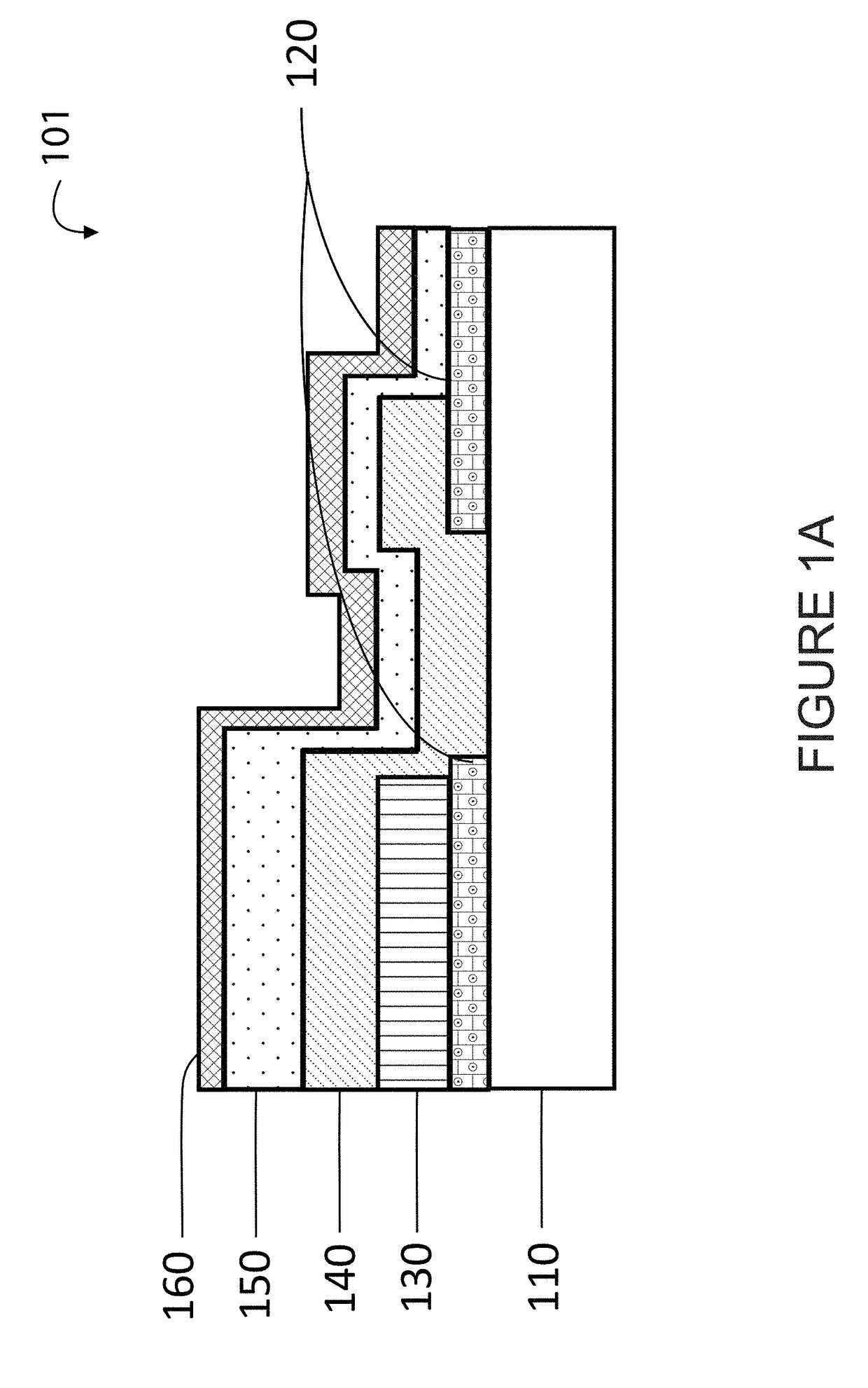
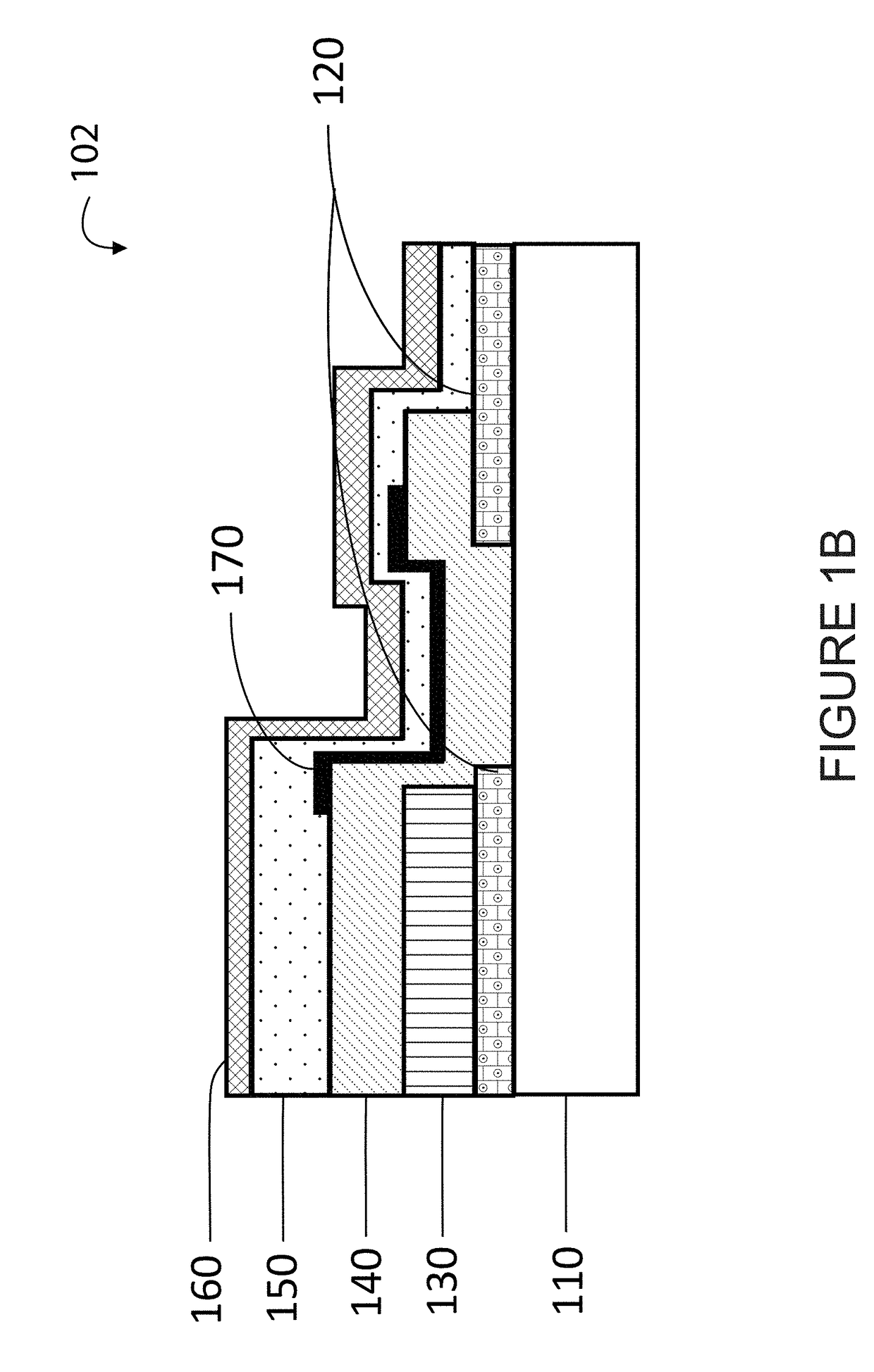
[0067]This example demonstrates the effect of a diffusion barrier interlayer within a thin film electrochemical system, which includes a substrate 110, a current collector 120, a cathode 130, an electrolyte 140, an anode 150, and an encapsulation layer 160 (shown in FIGS. 1A and 1B). FIG. 1A is a simplified cross-sectional view of thin film electrochemical energy storage cell according to an embodiment of present invention. FIG. 1A illustrates simplified cross-sectional views of electrochemical cell, 101, near the “bridge” region between cathode active area and anode current collector, where the lithium ion from anode is diffused through and forming the conductive pathway perpendicular to the substrate, across the anode and the anode current collector.

[0068]FIG. 1B is a simplified cross-sectional view of a modified thin film electrochemical cell, 102, with an additional diffusion barrier layer over the bridge region between the electrolyte and the anode layers according to an embodi...

example 2

[0079]When thin film electrochemical cells are stacked together, a set of electrochemical cells should be connected or isolated to form serial or parallel connections to establish desired voltages or capacities for a specific application. In this example, three lithium batteries are stacked to form three cells in parallel with an electrically isolating interlayer between stacks. Material types such as ceramics or polymers can be used as an isolating interlayer for stacked electrochemical cells with parallel connections. This example compares the effect of planarization of these two material types.

[0080]FIG. 5A is a scanning electron microscope graph of three stacks of thin film electrochemical energy storage cells without the interlayers and their cell voltages according to an embodiment of the present invention. In FIG. 5A, the voids under each interlayer is where a lithium layer exists. The wavy contour of the interlayer indicates that the top surface of the lithium was not flat. ...

example 3

[0083]As an example encountered by the battery designer, the value of intrinsic stresses distribution for a stacked electrochemical cells setup is unknown. Selection of the proper intermediate layer between layer 1 and layer 2 to reduce the stress is critical to construct a long cycle life battery. This example illustrates the effect of intermediate layer's modulus on stress distribution of stacked electrochemical cells by computer simulation.

[0084]FIG. 7 is a schematic drawing, specs and material properties of two thin film layers sandwiched an intermediate layer according to an embodiment of the present invention. The stacked electrochemical cells setup used in this example is composed of partially completed electrochemical cells, layer 1 and layer 2, as shown in FIG. 7. Modulus contrast ratio of the two layers, E2 / E1, is 10. Assuming there is an initial strain of 10% of e2 in layer 2.

[0085]FIG. 8 lists four different kinds of moduli of intermediate layer used in the simulation to...


PUM

PropertyMeasurementUnit
thicknessaaaaaaaaaa
thicknessaaaaaaaaaa
total thicknessaaaaaaaaaa

Abstract

A multi-layered solid-state battery device can have a substrate member having a surface region and a thin film battery device layer overlying the barrier material. The thin film battery device layer can comprise a cathode current collector, a cathode device, an electrolyte, an anode device, and an anode current collector. The device can have a non-planar surface region configured from the thin film battery device and a first polymer material overlying the thin film battery device and configured to fill in a gap region of the non-planar surface region and a planarizing surface region configured from the first polymer material.

Description

FIELD OF THE INVENTION[0001]The present invention relates generally to fabricating a thin film electrochemical energy storage device or a solid-state battery device. More particularly, the present invention provides techniques using multiple active layers and interlayers for the manufacture of a solid-state battery device.BACKGROUND OF THE INVENTION[0002]Common electro-chemical cells often use liquid electrolytes. Such cells are typically used in many conventional applications. Alternative techniques for manufacturing electro-chemical cells include solid-state cells. Such solid-state cells are generally in the experimental state, have been difficult to make, and have not been successfully produced in large scale. Although promising, solid-state cells have not been achieved due to limitations in cell structures and manufacturing techniques.SUMMARY OF THE INVENTION[0003]The present invention provides a method for fabricating a thin film electrochemical energy storage device or an all ...

Claims


Application Information

Patent Timeline
Patent Type & Authority Applications(United States)
IPC IPC(8): H01M10/0565H01M8/1086H01M10/0525H01M10/0585C08J5/22
CPCH01M10/0565H01M2300/0082H01M10/0436C08J5/22H01M10/0525H01M10/0585H01M6/40H01M10/05H01M10/0562Y02E60/10Y02P70/50
Inventor SASTRY, ANN MARIEWANG, CHIA-WEICHEN, YEN-HUNGKIM, HYONCHEOLZHANG, XIANGCHUNCHUNG, MYOUNGDO
Owner DYSON TECH LTD
Why Eureka
Try Eureka