Gas bearing substrate-loading mechanism process

A substrate and gas technology, applied in the direction of conveyors, electrical components, conveyor objects, etc., can solve problems such as not being raised

Inactive Publication Date: 2007-08-22
OERLIKON SOLAR IP
View PDF2 Cites 12 Cited by
  • Summary
  • Abstract
  • Description
  • Claims
  • Application Information

AI Technical Summary

Problems solved by technology

[0006] However, the prior art does not propose a solution to all of the above problems at the same time (like a lif

Method used


Image

  • Gas bearing substrate-loading mechanism process
  • Gas bearing substrate-loading mechanism process
  • Gas bearing substrate-loading mechanism process

Examples


example 1

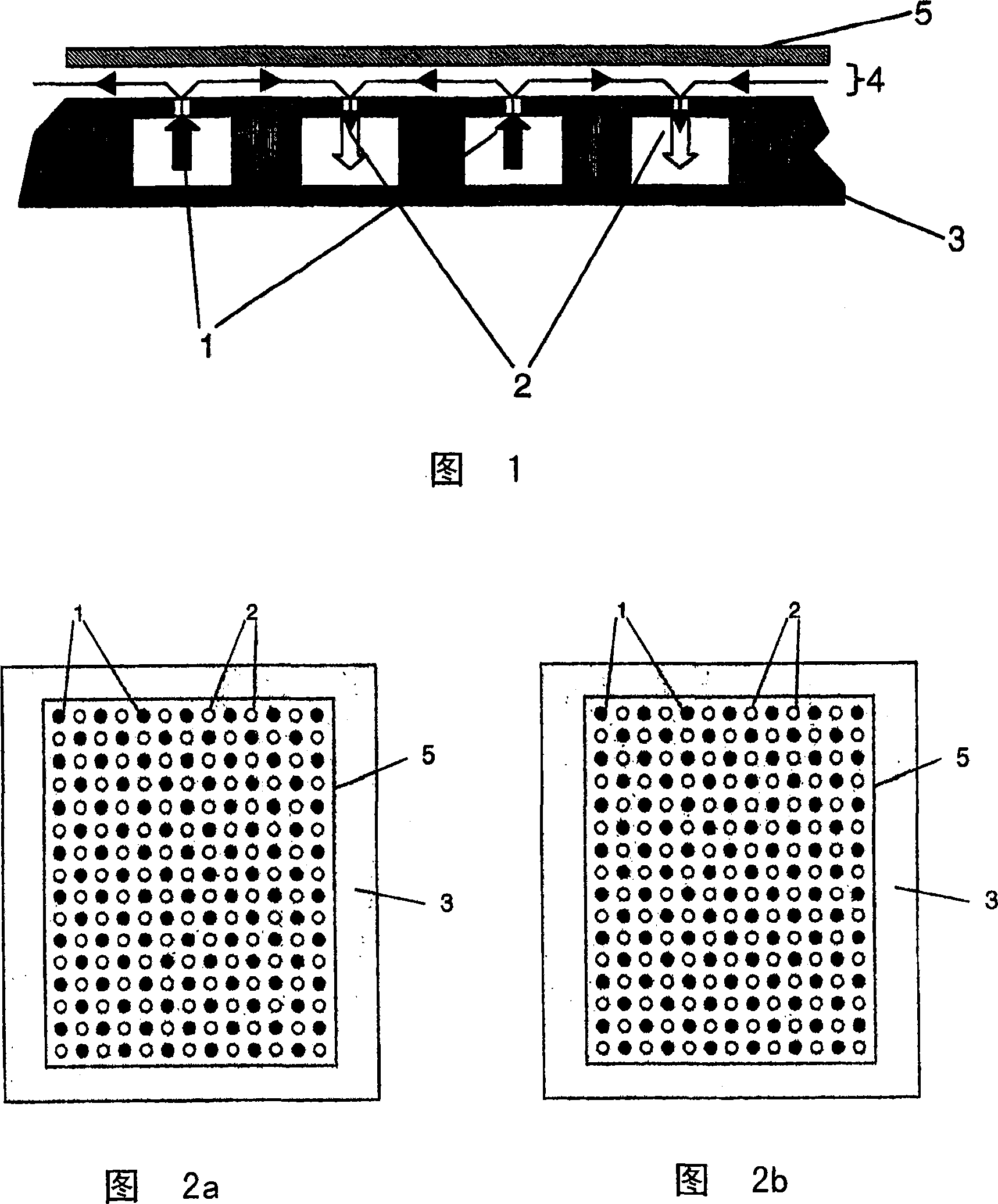
[0018] Example 1: Loading / unloading action by nitrogen injection, density 2700kg / m 3 A glass substrate having a thickness of 0.5 mm was suspended with a pressure of 100 Pa in the injection tank, a pressure of 50 Pa under the substrate and a pressure of 20 Pa in the suction tank.

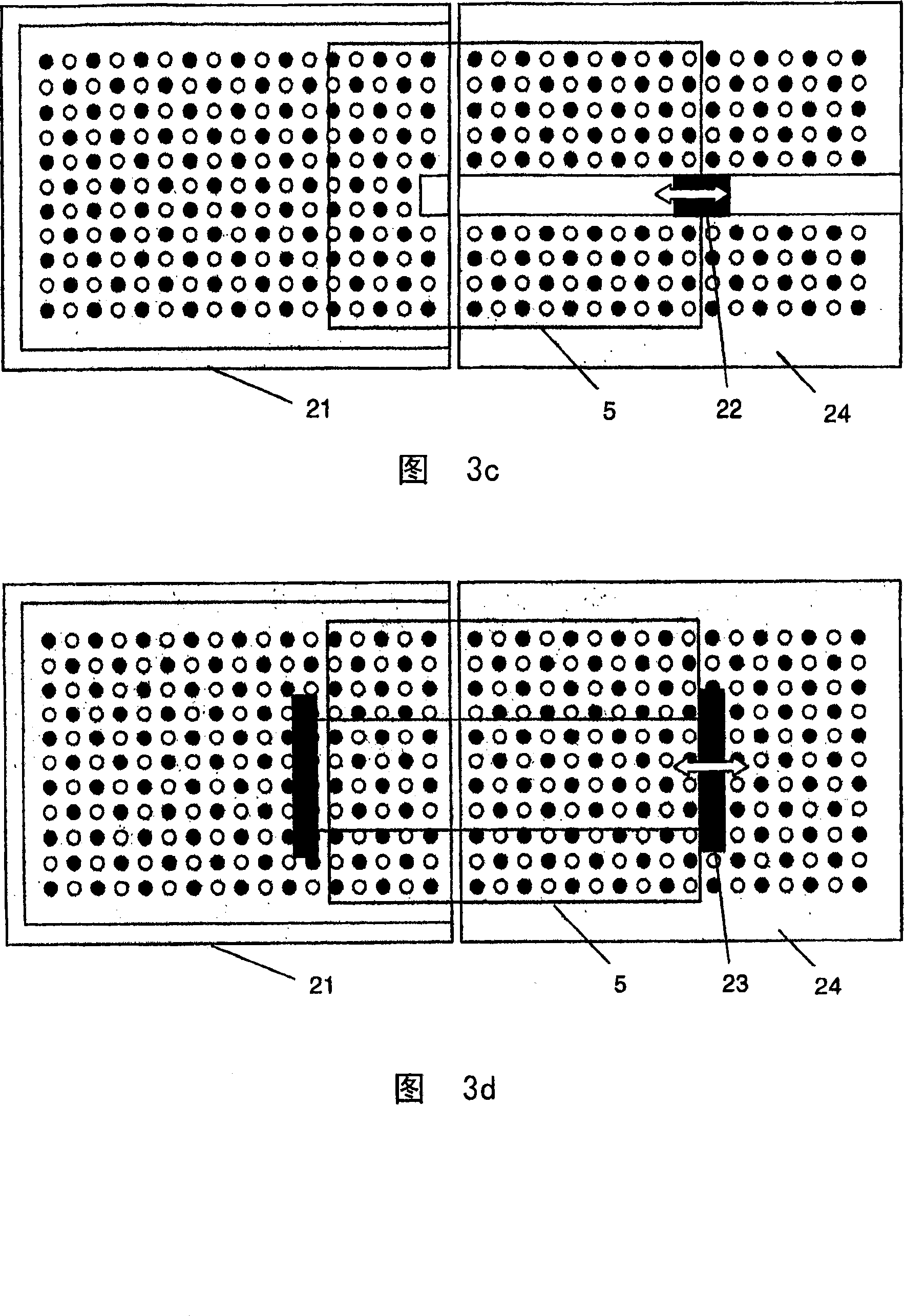
[0019] Because suction cups cannot be used in a vacuum, Figures 3a and 3b show a robotic device with a robotic table 24 with a clamping system 22 (clamps), in a preferred embodiment, once the aforementioned air cushion Levitating the substrate 5, the robotic table 24 is used to move the substrate 5, eg, into and out of the chamber (chamber bottom 21). Due to the suspension of the base 5 and because the loading and unloading movements take place in a substantially horizontal plane, only a small force is required to overcome the inertia of the base to move it to the final loading and unloading position. Alternatively, if the substrate is thick enough and rigid enough, the substrate can also be pushed ...


PUM


Abstract

A levitation apparatus for use under vacuum or near vacuum conditions comprises a levitation plate (3) with a plurality of injection points (1) and adjacent suction points (2) for gas, creating an air bearing (4) and thereby supporting a thin plate-like substrate (5). Further embodiments comprise a transport mechanism for supported substrates and/or a tilting mechanism to incline the levitation plate.

Description

Background of the invention [0001] The present invention relates generally to substrate motion in vacuum processing equipment, and in particular to multiple plasma-enhanced chemical vapor deposition (PECVD) reactors used in parallel in LCD production. The invention can also be used for substrate movement in other vacuums such as semiconductor wafers, optical or architectural glass, knives, and many different vacuum processes such as etching, sputtering, vapor deposition, chemical vapor deposition, etc. and many more Kind of basal movement. [0002] In many vacuum processing apparatuses, a substrate is loaded into a processing chamber by a load lock method so that a vacuum is constantly maintained in the actual processing chamber. [0003] For the loading and unloading of substrates under vacuum conditions from the load locks to the actual process chamber, as in semiconductor manufacturing installations, currently a combination of loading forks and lifting pins is mainly used....

Claims


Application Information

Patent Timeline
IPC IPC(8): B65G49/06B65G51/03
CPCH01L21/67748B65G2249/045B65G2249/04B65G51/03B65G2249/02B65G49/065H01L21/6838H01L21/02
Inventor V·卡萨格尼
Owner OERLIKON SOLAR IP
Why Eureka
Try Eureka