Channel determination method and used radio station and terminal equipment

A radio station, radio frequency technology, used in wireless communication, electrical components, communication between multiple stations, etc.

Inactive Publication Date: 2008-11-26
NEC CORP
View PDF5 Cites 0 Cited by
  • Summary
  • Abstract
  • Description
  • Claims
  • Application Information

AI Technical Summary

Problems solved by technology

[0015] In use Figure 18 In the explained conventional example of channel selection (decision) control, there is such a problem that communication interruption time is generated following channel decision, because in the decision channel, response request packet transmission process and response packet reception waiting process are performed by interrupting communication

Method used


Image

  • Channel determination method and used radio station and terminal equipment
  • Channel determination method and used radio station and terminal equipment
  • Channel determination method and used radio station and terminal equipment

Examples


no. 1 example

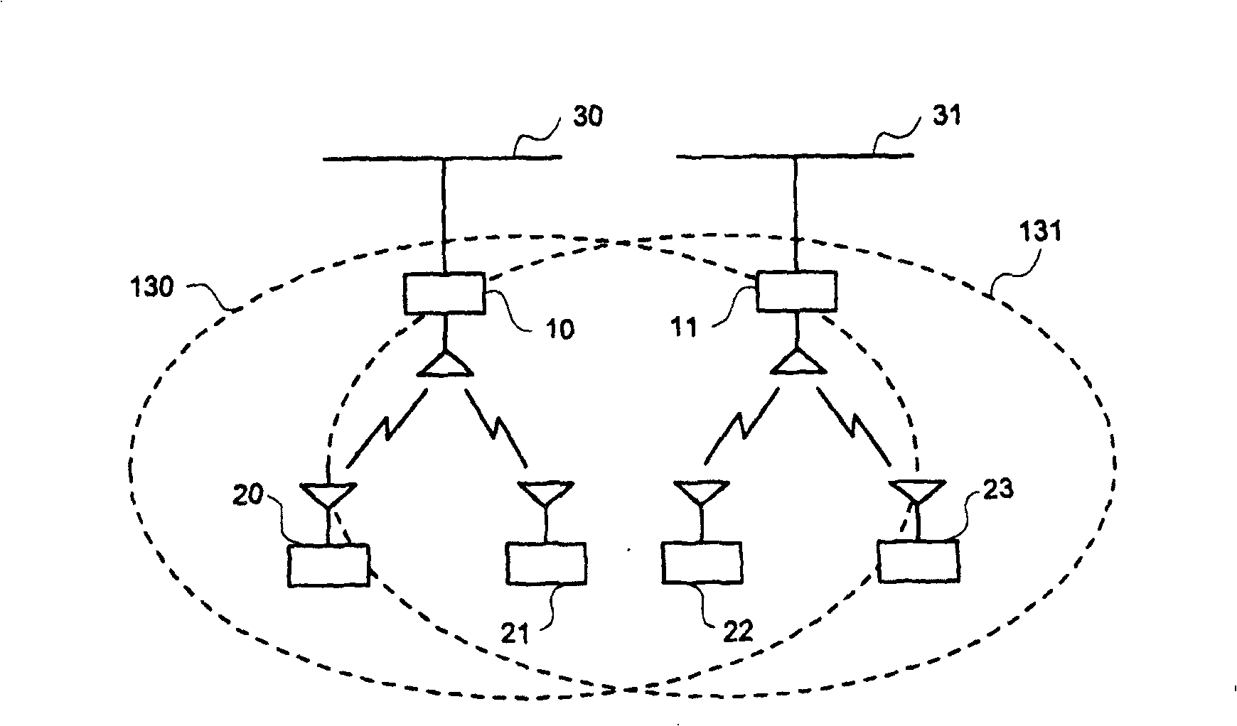
[0043] by using figure 1 , the first embodiment according to the present invention will be described in detail. Here, it is assumed that the radio base station 10 and the sub radio stations 20 and 21 are configured as the wireless network 130 conforming to the 802.11a standard, which is a wireless LAN specification for the 5 GHz band specified by IEEE.

[0044] The radio base station 10 provides a function of interconnecting the configured wireless network 130 and the wired network 30 . Similarly, the radio base station 11 and sub-radio base stations 22 and 23 conforming to the 802.11a standard are configured as another wireless network 131 . The radio base station 11 connects the wireless network 131 and the wired network 31 to each other.

[0045] The layers below the data link layer of the wired network 30 and the wired network 31 are not connected in this embodiment, but they may be connected. Such as figure 1 As shown, it is assumed that two wireless networks exist ...

no. 2 example

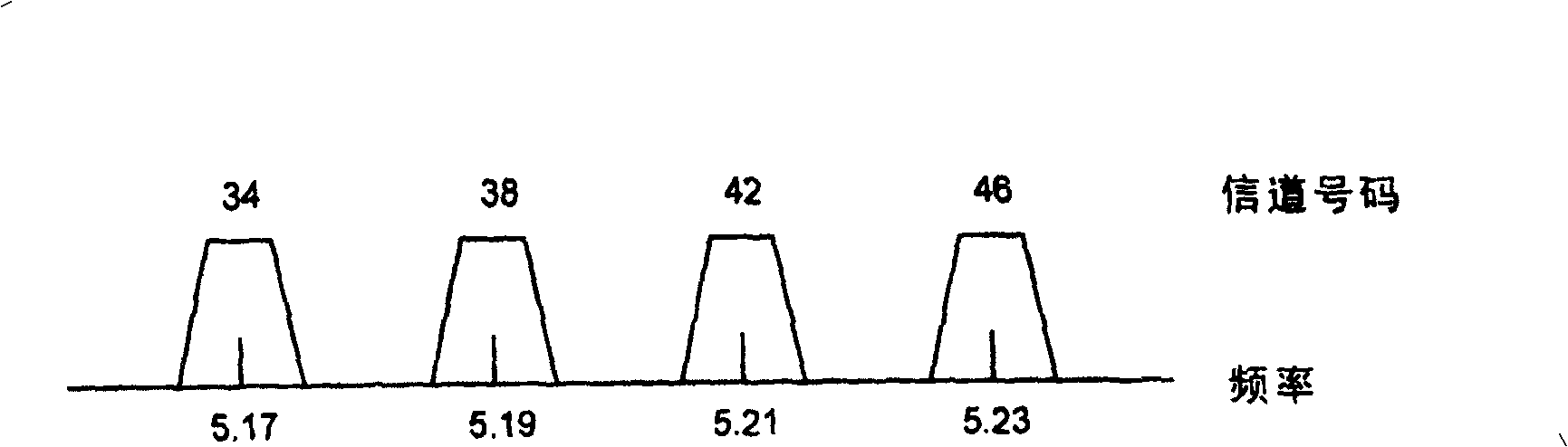
[0063] Next, a second embodiment of the present invention will be described in detail. Similar to the first embodiment is also adopted here figure 1 The network configuration shown. Similarly, the wireless LAN specification used in this embodiment is also the 802.11a standard, and the corresponding frequency channel is figure 2 The four channels shown in . However, it is assumed that the radio base station 10 having the internal configuration shown in FIG. 7 is used in the present embodiment.

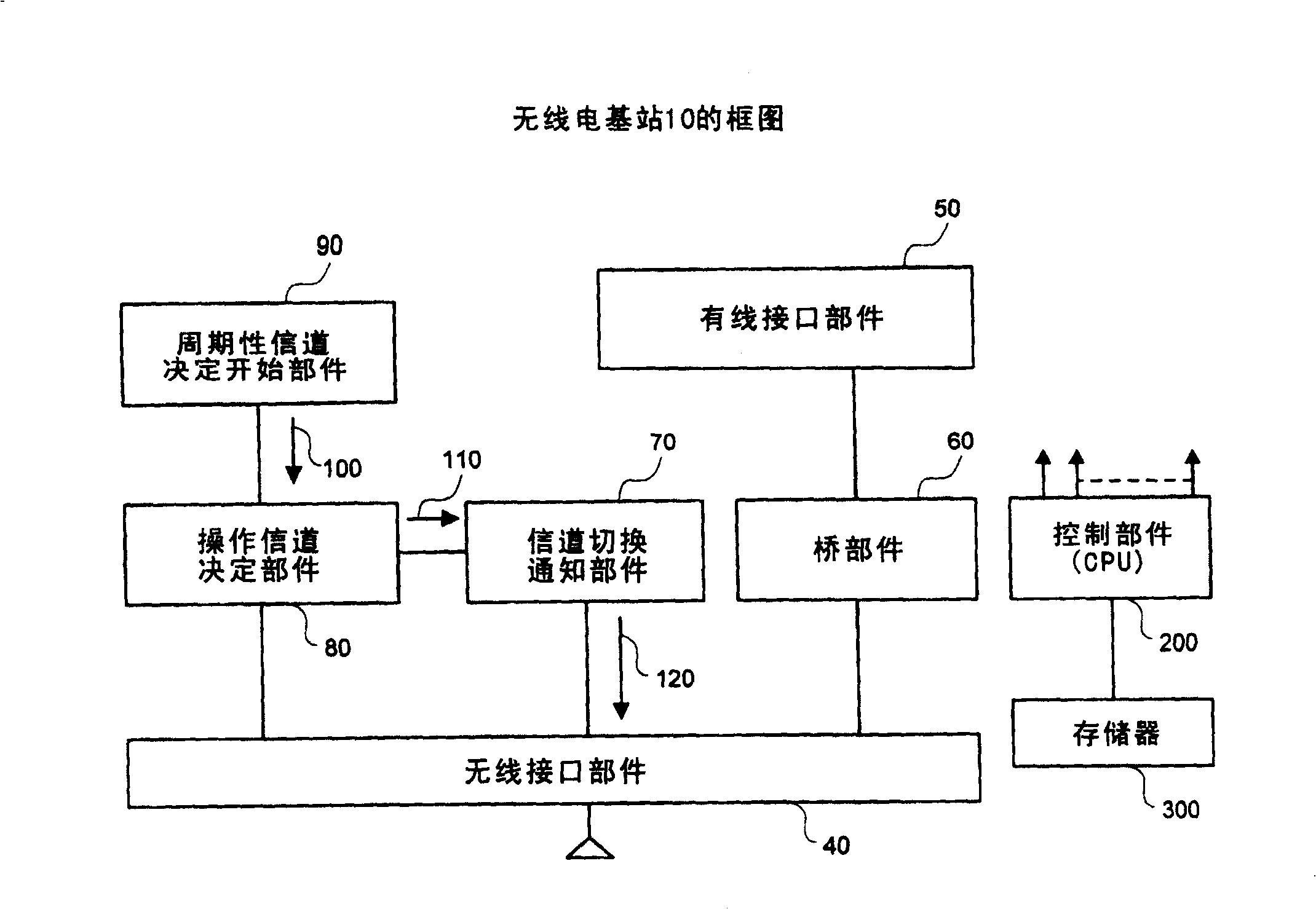
[0064] In Figure 7, with image 3 The equivalent part is shown with the same code, and its description is omitted. As shown in FIG. 7, the radio base station 10 used in this embodiment has a image 3 The interference amount determining part 140 and the logical sum (or) circuit 150 in the configuration of . That is, it is configured such that the logical sum of the channel decision start signal 100 sent from the periodic channel decision start section 90 and the channel decision ...

no. 3 example

[0075] Next, a third embodiment of the present invention will be described in detail. Similar to the first embodiment is also adopted here figure 1 The network configuration shown. Similarly, the wireless LAN specification used in this embodiment is also the 802.11a standard, and the corresponding frequency channel is figure 2 The four channels shown in . However, the radio base station 10 having the internal configuration shown in FIG. 10 is used in this embodiment.

[0076] In Figure 10, with image 3 The same portion as in Fig. 7 is shown with the same code, and its description is omitted. In Fig. 10, a channel quality storage unit 170 is added to the configuration of Fig. 7, and an operating channel decision unit 80 is adapted to refer to information 180 also stored in this channel quality storage unit 170 to decide a new operating channel.

[0077] The flow in the channel decision operation of this radio base station is the same as that of the radio base station 10...


PUM


Abstract

In a radio communication system adapted to decide one channel out of a plurality of radio frequency channels, and to cause communication to be made between a radio base station and a child radio station, decision of the channel is made at a periodic timing in the radio base station to notify information relating to this decided channel to the child radio station. Also, a configuration is made so that whenever the channel is decided and switched, communication quality (interference state) of its channel is detected in an interference quantity determination section 140 to make the channel decision by making a reference to this communication quality as well. By doing so, less communication interruption time occurs, and an influence that is given to communication performance of a wireless LAN can be reduced.

Description

technical field [0001] The present invention relates to a channel determination method and radio stations and terminal equipment for its use. More specifically, the present invention relates to a channel decision control technique adapted to avoid interference with other communication systems by switching a frequency channel used for communication in a radio communication system. Background technique [0002] Wireless local area networks (LANs), which excel in high speed, convenience, and cost-effectiveness, are rapidly spreading not only as conventional indoor LANs but also as public access networks in home LAN applications and public places. In general, compared with public mobile communication systems, wireless LANs are characterized by using a license-free frequency band, and since the frequency band is wide, the number of usable frequency channels is small (several channels or the like). Therefore, since the frequency channel used is the same as that of its adjacent wi...

Claims


Application Information

Patent Timeline
Patent Type & Authority Patents(China)
IPC IPC(8): H04B7/26H04L12/28H04W72/04H04W84/12
CPCH04W48/08H04W72/02H04W24/00H04W84/12
Inventor 土门涉冈上和广古川浩
Owner NEC CORP
Why Eureka
Try Eureka