Wireless transmission signal photovoltaic power station system

A photovoltaic power station and wireless transmission technology, applied in information technology support systems, electrical components, circuit devices, etc., can solve problems such as many fault points, long expansion cycle, repeated joint debugging, etc., to reduce communication interruption time and facilitate operation and maintenance, reducing the effect of unfavorable factors

Inactive Publication Date: 2016-01-20
JIANGSU HONGRI NEW ENERGY CO LTD
View PDF6 Cites 0 Cited by
  • Summary
  • Abstract
  • Description
  • Claims
  • Application Information

AI Technical Summary

Problems solved by technology

[0003] The traditional optical fiber ring network needs to add communication cabinets, communication management machines, and optical fiber switches to each photovoltaic array unit. The deployment of optical fiber cable has the problems of long cycle and poor flexibility; erecting optical fiber requires melting and embedding, and a large number of optical fibers are buried underground, which leads to maintenance. and maintenance difficulties, unable to quickly locate the problem
[0004] The reliability of the traditional optical fiber ring network depends on the ring network equipment and construction quality, and there are many fault points; and there are problems such as high cost of expansion, the need to lay new optical cables for expansion, long expansion period, and repeated joint debugging.

Method used


Image

  • Wireless transmission signal photovoltaic power station system
  • Wireless transmission signal photovoltaic power station system

Examples


Embodiment Construction

[0013] The present invention will be further described below in conjunction with specific drawings and embodiments.

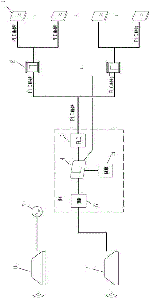
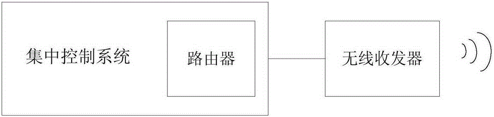
[0014] The wireless transmission signal photovoltaic power station system proposed by the present invention includes a centralized control system and a photovoltaic array unit; a centralized control system can wirelessly connect 20 to 30 photovoltaic array units; the number of photovoltaic array units depends on the installed capacity of the photovoltaic power station. And after expansion, it is convenient to connect with the centralized control system, and because of the wireless communication method, there is no need to re-lay optical cables.

[0015] Photovoltaic array unit among the present invention such as figure 1 As shown, it includes an inverter 1, a combiner box 2, a PLC module 3, a data collector 4, a box change controller 5, an adapter 6, a first wireless collection terminal 7, a second wireless collection terminal 8 and a video collection device 9;...


PUM


Abstract

The invention provides a wireless transmission signal photovoltaic power station system, which comprises a centralized control system and a photovoltaic array unit, wherein the centralized control system is connected with the photovoltaic array unit in a wireless communication mode; the photovoltaic array unit comprises an inverter, a combiner box, a PLC module, a data acquirer, a box substation measurement and control device, an adapter and a first wireless acquisition terminal; the input end of the inverter is connected with a photovoltaic panel; the output end of the inverter is connected with the combiner box; the combiner box is connected with the PLC module and the data acquirer; the signal output end of the box substation measurement and control device is connected with the data acquirer; and the data acquirer is connected with the first wireless acquisition terminal via the adapter. Wireless broadband transmission equipment is adopted to replace an optical fiber ring network, quick mounting can be realized, the data transmission network is more flattened and simplified, and operation and maintenance are facilitated; and trench excavation for burying optical cables for expansion is not needed, the expansion cost is low, and the expansion cycle is short.

Description

technical field [0001] The invention relates to a photovoltaic power station, in particular to a photovoltaic power station system in which monitoring data and production management data are transmitted through wireless communication. Background technique [0002] The photovoltaic power station system usually has a centralized control system and multiple photovoltaic array units; the optical fiber ring network is usually used to transmit data between the centralized control system and each photovoltaic array unit, for example, the monitoring data of the photovoltaic array unit is uploaded to the centralized control system, Production management data is bidirectionally circulated between the centralized control system and photovoltaic array units. [0003] The traditional optical fiber ring network needs to add communication cabinets, communication management machines, and optical fiber switches to each photovoltaic array unit. The fiber-optic cable deployment has the problem...

Claims


Application Information

Patent Timeline
Patent Type & Authority Applications(China)
IPC IPC(8): H02J13/00
CPCY04S40/126Y02E60/00
Inventor 王强郭清霄
Owner JIANGSU HONGRI NEW ENERGY CO LTD
Why Eureka
Try Eureka