
Method for manufacturing lamp bar and light guide board integrated structure, as well as mold and backlight module

A manufacturing method and technology for light guide plates, which are applied in the directions of optics, light guides, light sources, etc., can solve the problems of complicated processes of attaching light bars and light guide plates, and achieve the effects of reducing defects of light guide plates, reducing losses and improving light guide efficiency.

Active Publication Date: 2015-11-18
HEFEI BOE DISPLAY LIGHT +1
View PDF5 Cites 5 Cited by
  • Summary
  • Abstract
  • Description
  • Claims
  • Application Information

AI Technical Summary

Problems solved by technology

[0004] The object of the present invention is to provide a method for manufacturing an integrated structure of a light bar and a light guide plate and its mold, to produce an integrated light bar and light guide plate, and to solve the problem of attaching a light bar and a light guide plate when assembling a backlight module in the prior art The problem of complicated procedures; the present invention further provides a backlight module

Method used


Image

  • Method for manufacturing lamp bar and light guide board integrated structure, as well as mold and backlight module
  • Method for manufacturing lamp bar and light guide board integrated structure, as well as mold and backlight module
  • Method for manufacturing lamp bar and light guide board integrated structure, as well as mold and backlight module

Examples


Embodiment Construction

[0041] The specific implementation manners of the present invention will be further described in detail below in conjunction with the accompanying drawings and embodiments. The following examples are used to illustrate the present invention, but are not intended to limit the scope of the present invention.

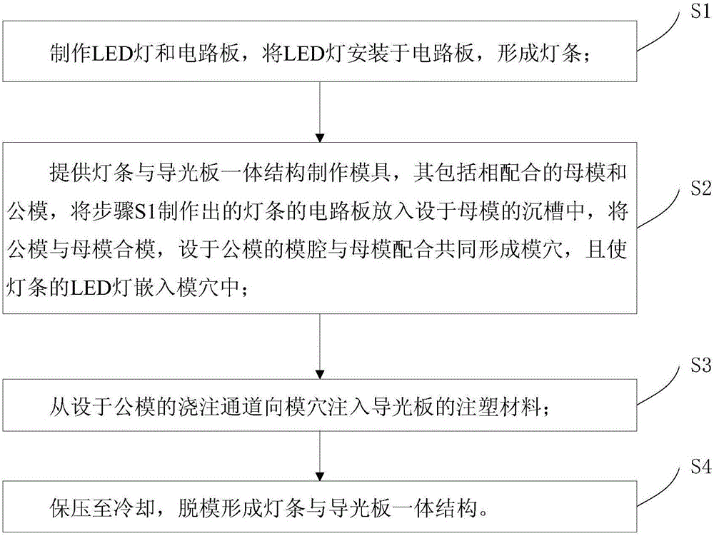
[0042] Such as figure 2 As shown, the manufacturing method of the integral structure of the light bar and the light guide plate of the present invention includes the following steps:

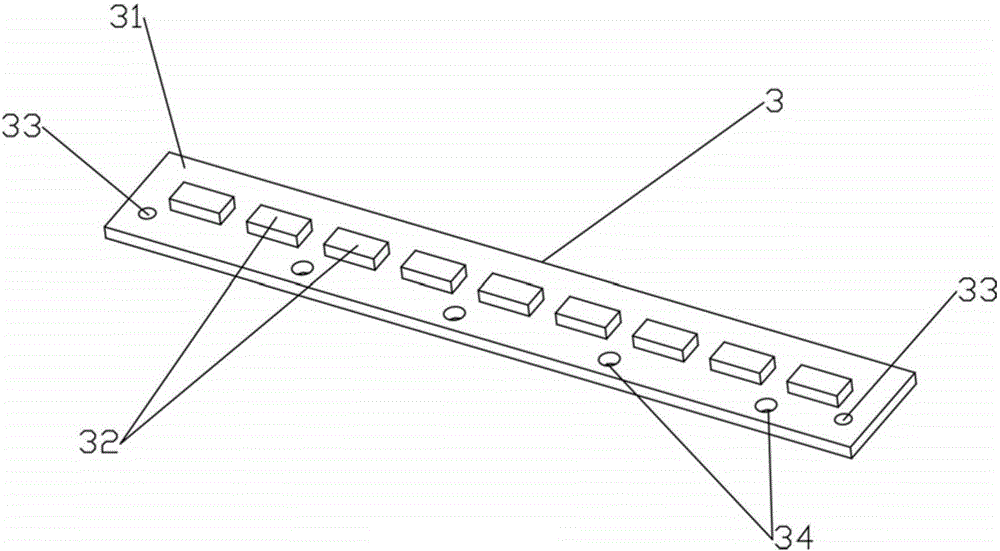
[0043] S1 , making the LED lamp 32 and the circuit board 31 , installing the LED lamp 32 on the circuit board 31 to form the light bar 3 . Step S1 specifically includes: S1.1, making the LED lamp 32, dehumidifying the LED lamp 32, and potting the surroundings of the LED lamp 32 with an organic potting glue; Stronger board, making circuit lines on the upper surface of the base material to form circuit board 31; S1.3, using solder paste to connect LED lamp 32 to circuit lines of circuit boa...


PUM


Abstract

The invention relates to the field of manufacture of backlight modules and discloses a method for manufacturing a lamp bar and light guide board integrated structure. The method comprises the following steps: S1, manufacturing LED lamps and a circuit board, and arranging the LED lamps on the circuit board so as to form a lamp bar; S2, providing a mold for manufacturing the lamp bar and light guide board integrated structure, wherein the mold comprises a female mold and a male mold which are matched with each other; putting the circuit board of the lamp bar manufactured in S1 in a sinking groove of the female mold, and assembling the male mold and the female mold, wherein a cavity of the male mold is matched with the female mold to form mold holes together, and the LED lamps of the lamp bar are embedded in the mold holes; S3, injecting injection molding materials of light guide boards into the mold holes from an injection molding channel of the male mold; and S4, keeping the pressure until the structure is cooled, and demolding to form a finished lamp bar and light guide board integrated structure. The lamp bar and light guide board integrated structure manufactured by adopting the method disclosed by the invention can be used for solving the problem that the process of sticking the lamp bar and the light guide board is complex in assembly of the backlight module. The invention further provides the mold for manufacturing the lamp bar and light guide board integrated structure, and the backlight module.

Description

technical field [0001] The invention relates to the field of backlight module manufacturing, in particular to a method for manufacturing an integral structure of a light bar and a light guide plate, a mold thereof, and a backlight module. Background technique [0002] Such as figure 1 As shown, the backlight module in the prior art includes a backplane 101, a light guide plate 102, a light bar 103, a reflector 104, and an optical film 105, and the reflector 104, the light guide plate 102, and the optical film 105 are sequentially stacked on the backplane. 101 on the front surface, the light bar 103 is disposed on one side of the light guide plate 102 . According to the prior art, in the process of assembling the backlight, the light guide plate 102 needs to be attached to the light bar 103 first, then the reflective sheet 104 is assembled into the back plate 101, and finally the light bar 103 and the light guide plate 102 are integrally assembled. into the backplane. In t...

Claims


Application Information

Patent Timeline
Patent Type & Authority Applications(China)
IPC IPC(8): F21S8/00F21V17/00F21V19/00F21V23/06F21V8/00F21Y103/00F21Y101/02
CPCF21S8/00F21V17/00F21V19/001F21V19/0035F21V19/005F21V23/06
Inventor 朱智韦飞薛银艳钱叶甲张强
Owner HEFEI BOE DISPLAY LIGHT
Learn More