Energy-efficient distillation system

Inactive Publication Date: 2009-09-03
SYLVAN SOURCE
View PDF5 Cites 32 Cited by
  • Summary
  • Abstract
  • Description
  • Claims
  • Application Information

AI Technical Summary

Benefits of technology

[0012]Also disclosed herein is a method of recovering heat within a fluid distillation system. The method includes passing fluid through a heat-yielding purification element of the fluid distillation system. Latent heat energy can be absorbed from the heat-yielding purification element. The latent heat energy can then be transferred from the heat-yielding purification element to a fluid within the fluid inlet of the fluid distillation system without direct contact between the fluid inlet and the purification element, causing the fluid to be heated. In some aspects, also included is the step of reducing scale formation of the fluid by exciting ions within the

Problems solved by technology

This evaporation process is energy intensive because of the high value of the latent heat of evaporation of water at boiling temperatures of 100 degrees Celsius (100° C.
Because conductivity is the basic mechanism of heat transfer for all heat exchangers, they are normally designed to maximize the surface area of contact between the hot and cold fluid, and the consequence of such design is that heat exchangers are generally bulky, heavy, and expensive pieces of equipment.
In addition, large surfaces that are warmer than the surrounding air lose heat to the environment and, since cost limits the amount of surface area that can be provided in any given configuration, heat exchangers typically have low thermal effici

Method used


Image

  • Energy-efficient distillation system
  • Energy-efficient distillation system
  • Energy-efficient distillation system

Examples


Embodiment Construction

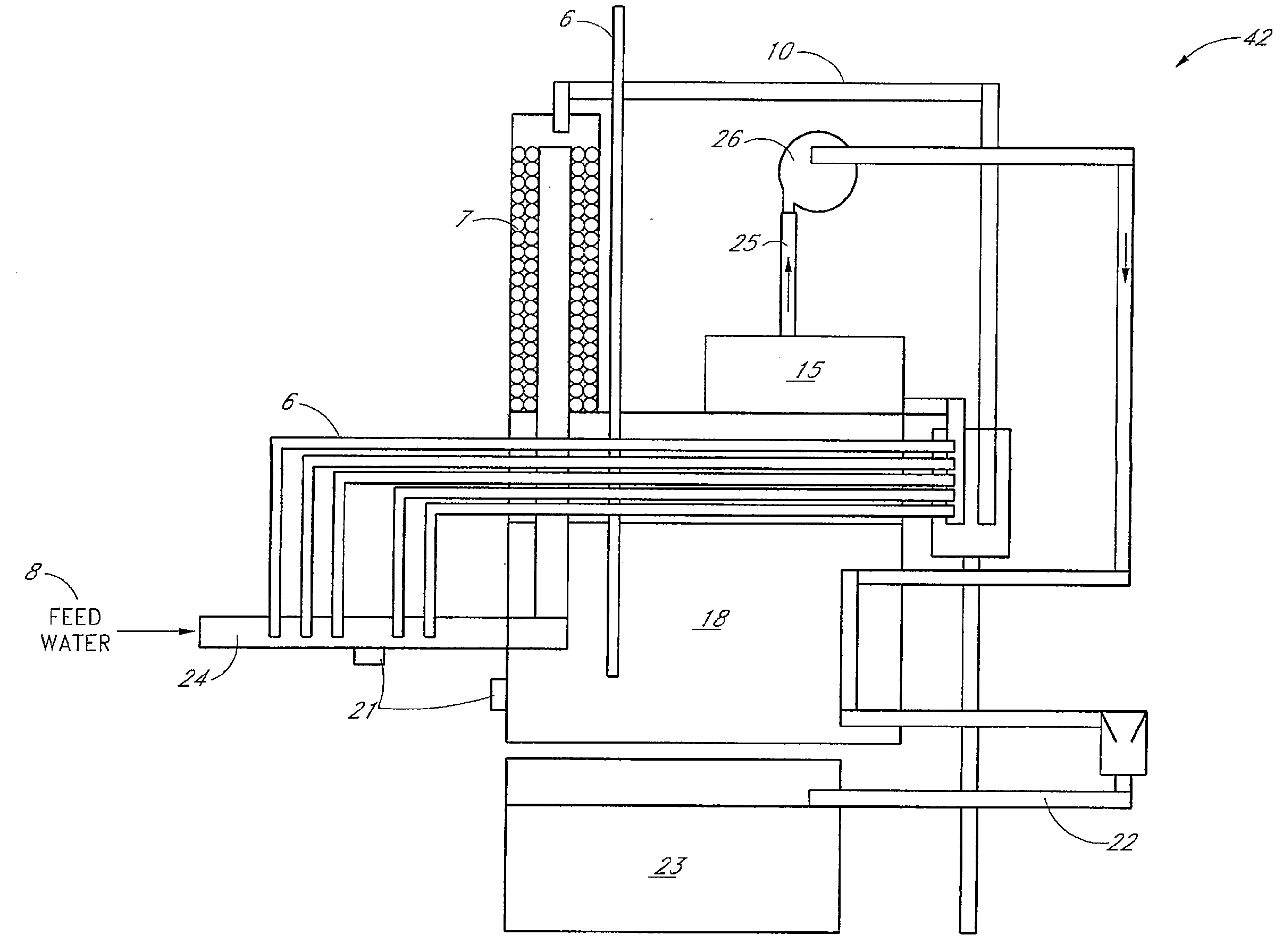
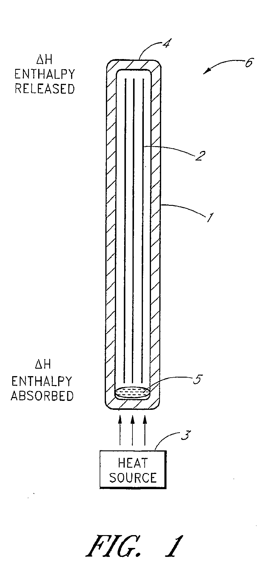
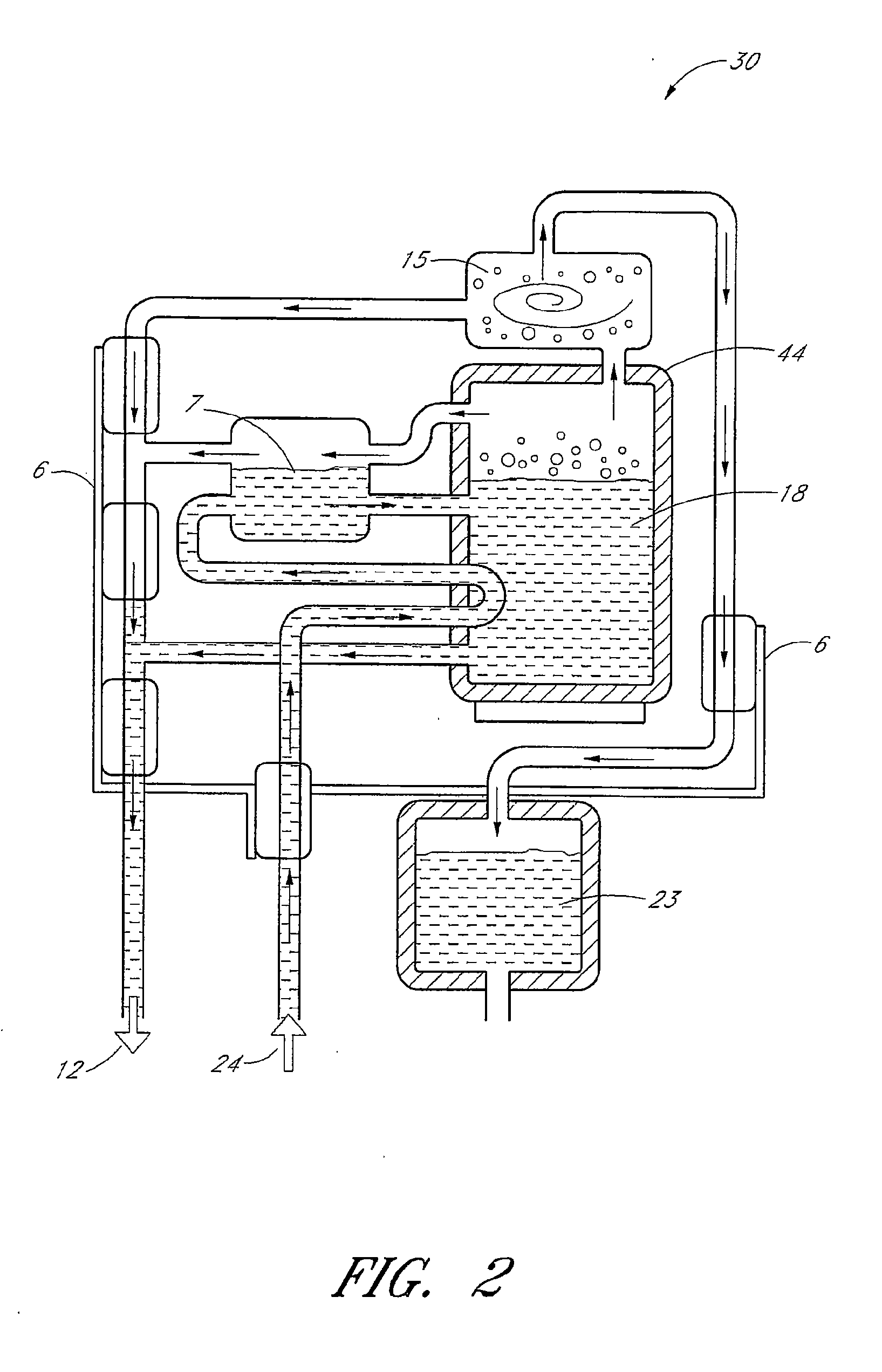
[0022]The present invention includes a compact, more effective heat recycling system that can be utilized to recover heat from distillation units without the need for heat exchangers. The inventive concept includes using different configurations of heat pipes that transfer heat from hot waste or product streams to an incoming feed fluid, e.g., water, so as to minimize overall heat requirements for a fluid purification system. Heat pipes rely on the principle of enthalpy transport to transfer heat from one point to another, and they normally require a phase change in the fluid used to transfer heat. Because phase change, from liquid to vapor or solid to vapor (e.g., sublimation) or vice-versa, is always associated with the heat of vaporization or condensation (or heat of sublimation in the case of solids), and because such heats of vaporization are normally very substantial when compared with the specific heat conductivities of most materials, the intrinsic efficiencies of a heat pip...


PUM

PropertyMeasurementUnit
Vapor pressureaaaaaaaaaa
Magnetic energyaaaaaaaaaa

Abstract

Methods and devices are provided for an energy-efficient distillation system (42). An energy-efficient distillation system (42) can include a fluid inlet (24), one or more heat-yielding purification elements (7, 15, 44) downstream of the fluid inlet (24), one or more heat pipes (6), and a fluid outlet (23) downstream of the heat-yielding purification element (7, 15, 44). The heat-yielding purification element (7, 15, 44) can be, for example, a degasser (7), a demister (15), or an evaporation chamber (44). A heat pipe (6) has a first end operably connected to the heat-generating purification element(s) (7, 15, 44), a second end operably connected to the fluid inlet (24), and a body therebetween. The heat pipe (6) is configured to transfer latent heat energy from the first end to the second end, thereby heating a fluid (8) within the fluid inlet (24). The distillation system (42) can also include one or more descaling elements (21) for reducing scale formation of the fluid (8).

Description

RELATED APPLICATIONS[0001]This application claims the benefit under 35 U.S.C. § 119 of U.S. Provisional Application No. 60 / 727,106 filed Oct. 14, 2005 and U.S. Provisional Application No. 60 / 748,496 filed Dec. 7, 2005. The priority applications are hereby incorporated by reference herein in their entirety.BACKGROUND OF THE INVENTION[0002]1. Field of the Invention[0003]This invention relates to an energy efficient distillation system.[0004]2. Description of the Related Art[0005]All distillation systems used for water purification rely on the evaporation of water containing contaminants, so as to produce steam which is essentially free of contaminants. This evaporation process is energy intensive because of the high value of the latent heat of evaporation of water at boiling temperatures of 100 degrees Celsius (100° C.), or 212 degrees Fahrenheit (212° F.), which is known to be 539.55 calories per gram (971.19 Btu / lb). This amount of energy is in addition to the energy required to bri...

Claims


Application Information

Patent Timeline
IPC IPC(8): B01D1/30B01D3/00B01D5/00B01D19/00
CPCB01D1/305B01D19/001B01D5/0039B01D3/007
Inventor DEMMONS, LAURATHIERS, EUGENE
Owner SYLVAN SOURCE
Why Eureka
Try Eureka