
An enhanced OTDR tail fiber test auxiliary device

A technology of auxiliary device and test device, which is applied in the direction of measuring device, optical instrument test, machine/structural component test, etc., can solve the problem of not being able to correctly judge the position of the breakpoint of the optical cable, shorten the communication interruption time, increase the distance, and achieve considerable The effect of economic and social benefits

Pending Publication Date: 2019-05-21
STATE GRID CORP OF CHINA +1
View PDF8 Cites 0 Cited by
  • Summary
  • Abstract
  • Description
  • Claims
  • Application Information

AI Technical Summary

Problems solved by technology

[0004] The purpose of the present invention is to solve the problem that the breakpoint position of the optical cable cannot be correctly judged by the OTDR when the fault point of the optical cable is in the blind area of ​​the OTDR, and proposes an enhanced OTDR pigtail test auxiliary device

Method used


Image

  • An enhanced OTDR tail fiber test auxiliary device
  • An enhanced OTDR tail fiber test auxiliary device
  • An enhanced OTDR tail fiber test auxiliary device

Examples


specific Embodiment approach 1

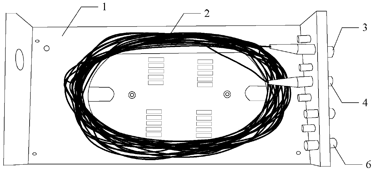
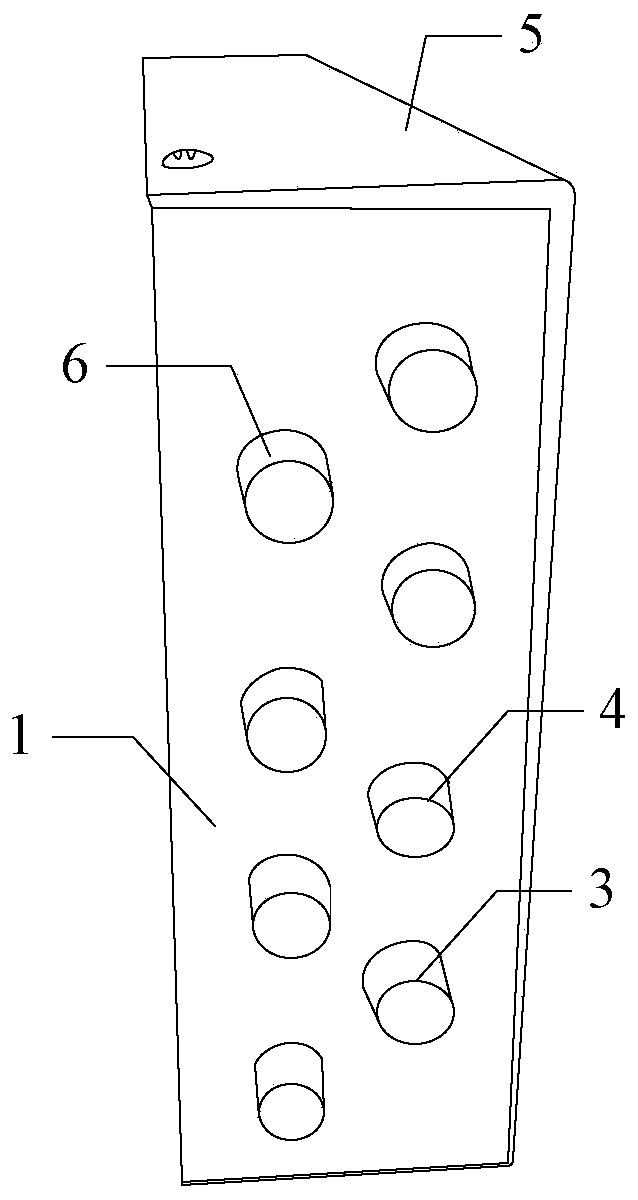
[0015] Specific implementation mode one: combine Figure 1 to Figure 3 Describe this embodiment, an enhanced OTDR pigtail test auxiliary device described in this embodiment includes a base 1, an auxiliary pigtail 2, a first flange head connector 3, a second flange head connector 4 and a top cover 5;

[0016] The base 1 and the top cover 5 form a box structure, and the auxiliary pigtail 2 is arranged inside the box; the seat 1 and the top cover 5 form a box structure for protecting the auxiliary pigtail 2;

[0017] The first flange head connector 3 and the second flange head connector 4 are respectively arranged on the side wall of the end of the base 1; the first flange head connector 3 and the second flange head connector 4 are used for convenient auxiliary Pigtail 2 is connected between the optical cable under test and the OTDR;

[0018] One end of the auxiliary pigtail 2 is connected to the inner end of the first flange head connector 3, the other end of the auxiliary pig...

specific Embodiment approach 2

[0021] Specific embodiment two: this embodiment further limits the enhanced OTDR pigtail test auxiliary device described in specific embodiment one. In this embodiment, the base 1 is provided with a pigtail slot;

[0022] The auxiliary pigtails 2 are coiled in the pigtail groove in a helical arrangement.

[0023] In this embodiment, the auxiliary pigtails 2 are prevented from being damaged by setting the pigtail slots and limiting the distribution of the auxiliary pigtails 2 .

specific Embodiment approach 3

[0024] Specific embodiment three: this embodiment further limits the enhanced OTDR pigtail test auxiliary device described in specific embodiment two, in this embodiment, the test device also includes a strap;

[0025] The strap is used to fix the auxiliary pigtail 2 in the pigtail groove.

[0026] In this embodiment, the auxiliary pigtail 2 is fixed by straps to ensure that the auxiliary pigtail 2 will not be damaged due to transportation or movement in the box composed of the base 1 and the top cover 5 .


PUM


Abstract

The utility model discloses an enhanced OTDR (Optical Time Domain Reflectometer) tail fiber test auxiliary device, relates to a short-distance optical cable fault point searching technology, and aimsto solve the problem that the position of an optical cable breakpoint cannot be correctly judged through an OTDR when an optical cable fault point is in a blind area of the OTDR. A box body structureis formed by a base and a top cover, and an auxiliary tail fiber is arranged in a box body; The first flange head connector and the second flange head connector are respectively arranged on the side wall of the end part of the base; One end of the auxiliary tail fiber is connected with the inner end of the first flange head connector, the other end of the auxiliary tail fiber is connected with theinner end of the second flange head connector, the outer end of the first flange head connector is used for being connected with a tested optical cable, and the outer end of the second flange head connector is used for being connected with an OTDR optical output port through the connecting tail fiber. The beneficial effects are that accurate positioning of short-distance fault points of the optical cable is realized; The method is suitable for searching the short-distance fault point of the optical cable.

Description

technical field [0001] The invention relates to a technology for finding fault points of short-distance optical cables. Background technique [0002] When using an optical time domain reflectometer (OTDR) to measure an optical cable, firstly connect the pigtail to the optical output port of the OTDR correctly through the movable connector, press the power switch, and wait for the clear menu graphics to appear on the LCD screen, then press the function key, Set the OTDR distance, refractive index, average time, pulse width, wavelength and other parameters, and finally press the laser emission button, so that the optical pulse generated by the OTDR is transmitted to the line through the pigtail; The information is analyzed, and a certain waveform is formed on the LCD screen to display parameters such as cable length, breakpoint position, joint position, attenuation coefficient, link loss, and reflection loss. [0003] In the process of finding the fault point of the optical c...

Claims


Application Information

Patent Timeline
Patent Type & Authority Applications(China)
IPC IPC(8): H04B10/071G01M11/00
Inventor 高玉梅袁晋昌王占伟谢岩张国歌陈卓薛军荆杰韩艳辉田耕谭凤洁张淑艳田子佳王立波薛铭轩
Owner STATE GRID CORP OF CHINA
Learn More