Image compensating correcting method for light-source fixed scanner

A scanner and light source technology, applied in image communication, electrical components, etc., can solve problems such as the increase in the volume occupied by optical machines

Inactive Publication Date: 2008-11-26
TRANSPACIFIC SYST
View PDF4 Cites 0 Cited by
  • Summary
  • Abstract
  • Description
  • Claims
  • Application Information

AI Technical Summary

Problems solved by technology

And because the light source is configured on the optical machine, adding a light collector above the light source to concentrate the light from the light source can improve the above problems, but this will increase the volume of the entire light machine (including the added light collector) , contrary to the current trend of electronic product design towards miniature

Method used


Image

  • Image compensating correcting method for light-source fixed scanner
  • Image compensating correcting method for light-source fixed scanner
  • Image compensating correcting method for light-source fixed scanner

Examples


Embodiment Construction

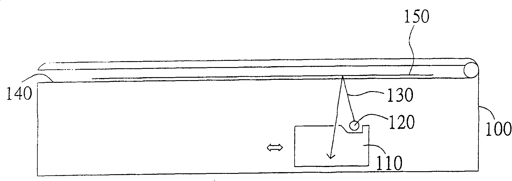
[0014] The image compensation correction method of the fixed light source scanner of the present invention is to fix the light source in the scanner, add a light collector to improve the lighting efficiency, and provide a variable current for the light source, so that each scanning line on the document can receive The exposure levels are the same.

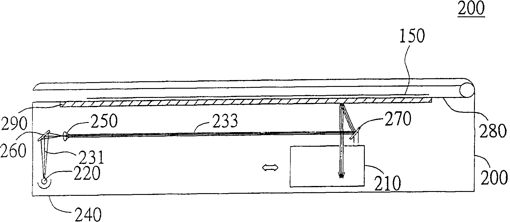
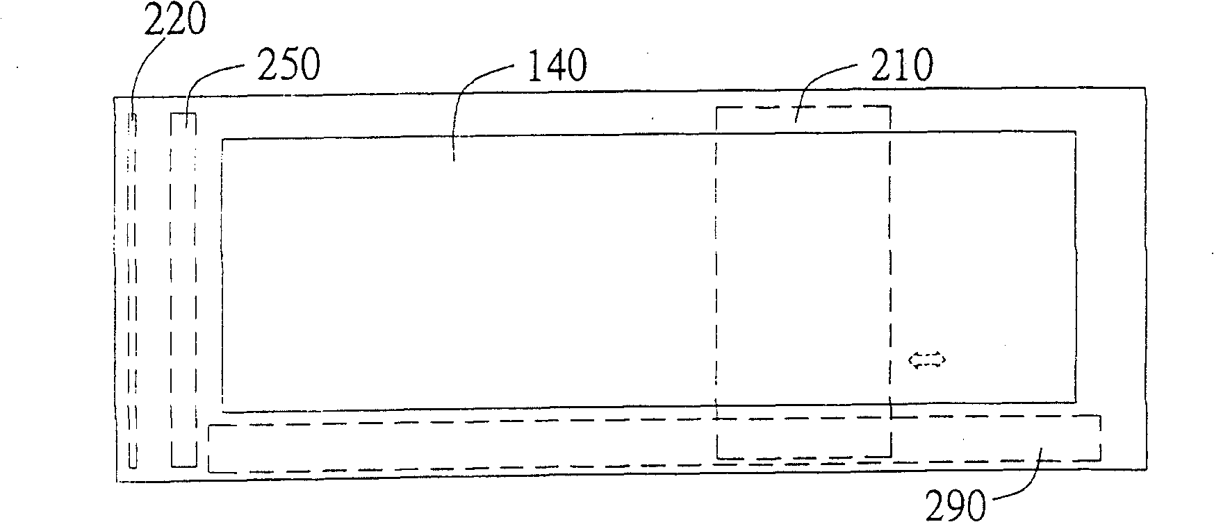
[0015] Please refer to figure 2 , which is a cross-sectional view of a light source fixed scanner. The light source 220 is fixed on the side of the scanner housing 200 close to the housing 200, for example placed on the lower wall 240 of the scanner housing, and the light collector 250 formed by the lens group is arranged near the light source 220 for The light 231 emitted by the light source 220 is concentrated into a parallel light beam 233 with an appropriate width. Wherein, in accordance with the position of the light source 220 , a lens (such as a reflector 260 ) may be added to bend the light 231 to the light collector 250...


PUM


Abstract

A method for image compensation and correction is used for the fixed light source type scanner. The fixed light source is fixed in the chassis of scanner, and the optical collector is added to promote lighting efficiency. The reference board is attached the medial surface of superior wall of the scanner chassis for making scanning correction. The method provides light source with variation current to make the brilliancy of light source changed along with the changing of light emitting device position, makes the each scan line illuminated equally. The steps includes moving the light emitting device into different position, and scanning the referent board with a fixed brilliant light source to produce the relevant brightness value corresponding to the optical mechanical device position, then according to each relevant brightness value calculating the compensation value for each light emitting device position.

Description

(1) Technical field [0001] The present invention relates to an image compensation and correction method, and in particular to an image compensation and correction method for a scanner with a fixed light source (2) Background technology [0002] With the advent of the multimedia era, the use of scanners is becoming more and more common. Users' requirements for scanning quality and speed are also gradually increasing, and their preferences for appearance and shape tend to be thinner and shorter. [0003] Please refer to figure 1 , which is a cross-sectional view of a general flatbed scanner. Inside the scanner housing 100 is an optical machine 110 that has an image receiving function and can move back and forth parallel to the scanner housing 100 . The optical machine 110 has a light source 120 . During scanning, the light emitted by the light source 120, such as the light 130, hits the document 150 on the glass platform 140, is reflected by the document 150 and enters the o...

Claims


Application Information

Patent Timeline
Patent Type & Authority Patents(China)
IPC IPC(8): H04N1/04
Inventor 曾文昭
Owner TRANSPACIFIC SYST
Why Eureka
Try Eureka