Latex electrodeposition device

An electrodeposition device and latex technology, applied in the field of rubber processing, can solve the problems of large corrosion of equipment, increased solid colloids, long acid solidification time, etc., and achieve the effect of leveling the liquid level

Active Publication Date: 2020-01-17
海南省先进天然橡胶复合材料工程研究中心有限公司
View PDF8 Cites 0 Cited by
  • Summary
  • Abstract
  • Description
  • Claims
  • Application Information

AI Technical Summary

Problems solved by technology

[0002] The coagulation of latex is an important link that affects the quality of rubber. Existing processing plants all use coagulants such as formic acid, acetic acid, sulfuric acid, and inorganic salts to coagulate. Although this method requires simple and easy-to-operate equipment and processes, it also has many shortcomings: 1. .Acid coagulation time is long, product quality is difficult to control, unstable and continuous production capacity is poor; 2. The product has a strong taste, which is harmful to the human body; 3. Acid corrodes equipment, etc., which limits its industrialization degree
[0004] During the electrodeposition process, the positive electrode reactor is in contact with the surface of the glue in the negative electrode tank, and the latex will form a gel film on the surface of the positive electrode reactor, so it is easy for the glue block to solidify at both ends of the positive electrode reactor. The gel film cannot be collected by the positive electrode reactor in a timely and complete manner, which can easily lead to the increase and accumulation of deposited solid colloids in the negative electrode pool, thereby affecting the continuous extraction of latex. As the solid colloids gradually accumulate in the negative electrode pool, resulting in The volume of the deposited solid colloid is too large, and gradually approaches the liquid surface of the glue solution, thus affecting the uniform roll-up of the gel film and affecting the use of the subsequent gel film

Method used


Image

  • Latex electrodeposition device
  • Latex electrodeposition device
  • Latex electrodeposition device

Examples


Embodiment Construction

[0021] In order to better understand the technical content of the present invention, specific embodiments are provided below, and the present invention is further described in conjunction with the accompanying drawings.

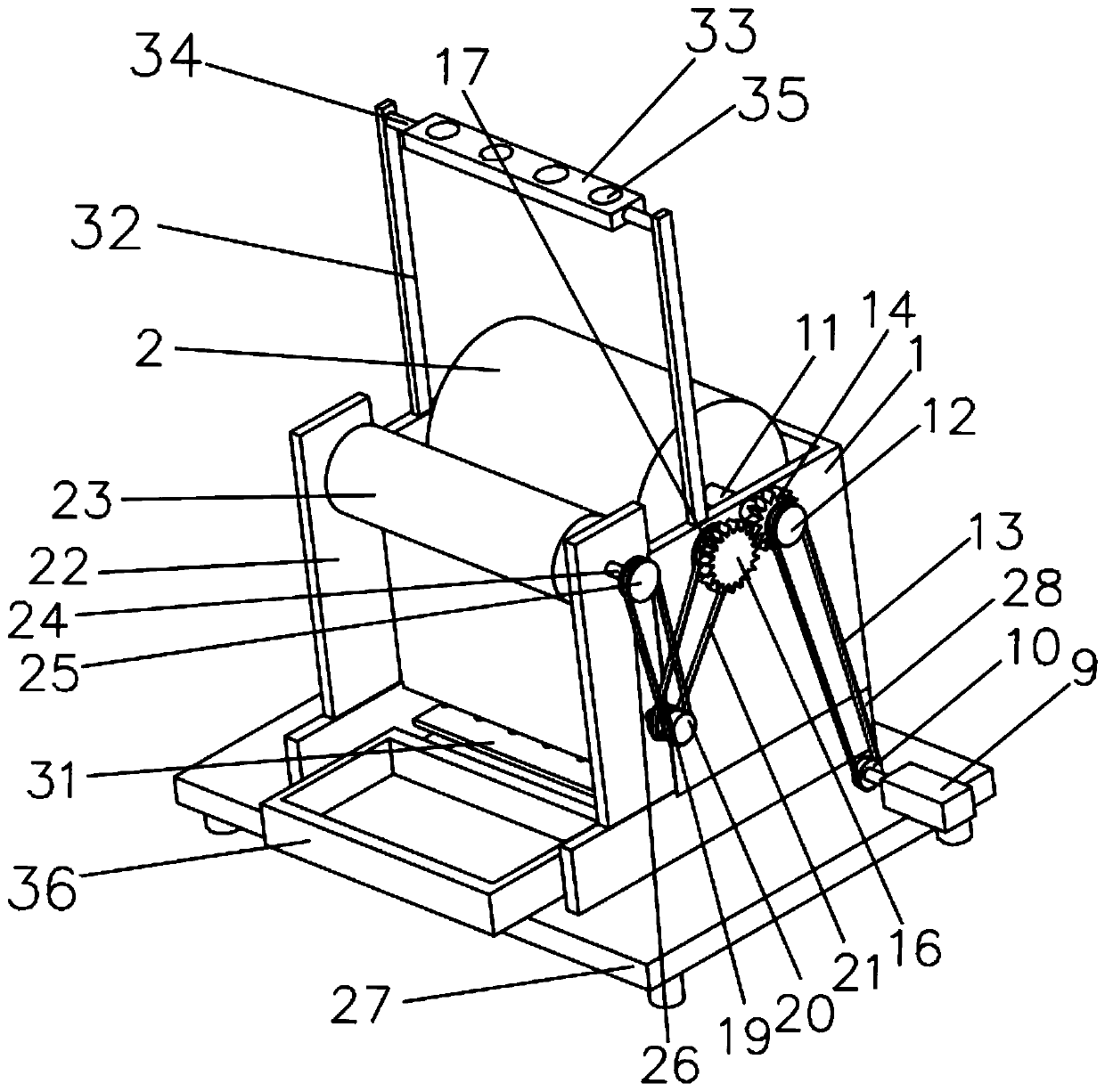
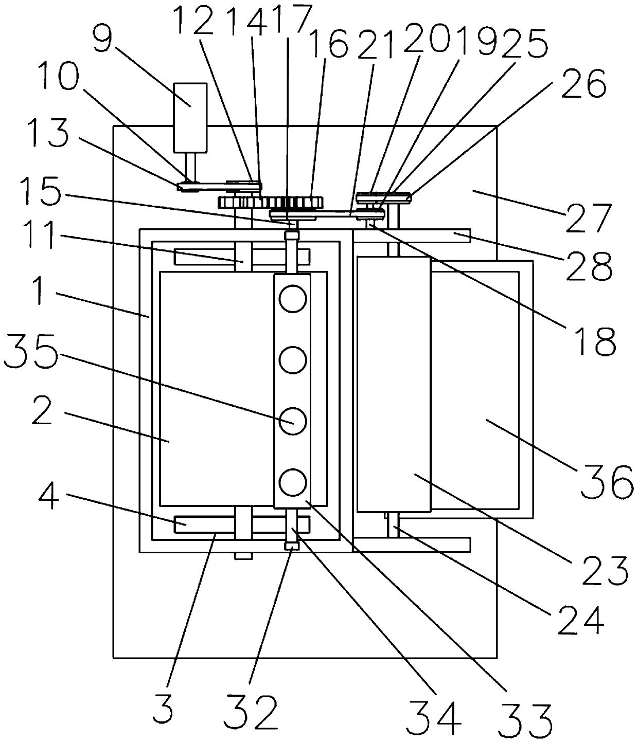
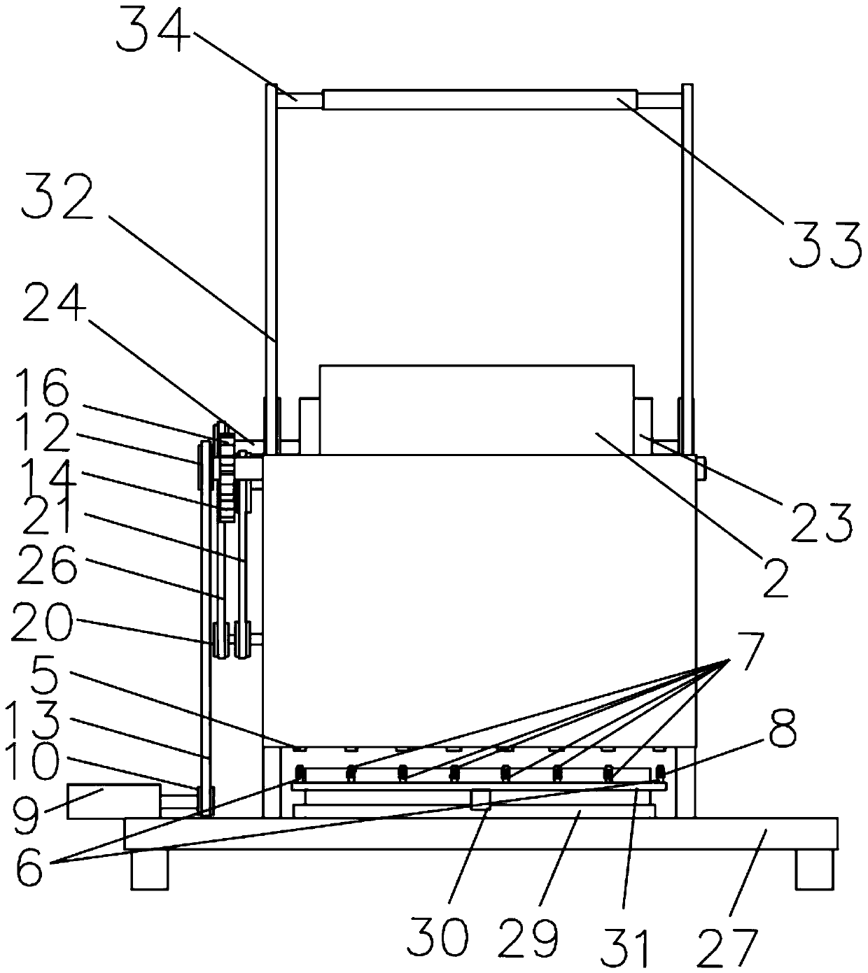
[0022] see Figure 1 to Figure 4, a latex electrodeposition device of the present invention includes a negative electrode pool 1 for holding glue and a drive mechanism, which can continuously add glue into the negative electrode pool 1 during the electrodeposition process to ensure that the negative electrode pool 1 The change of the liquid level is small, the output end of the drive mechanism is provided with a positive electrode reactor 2, which is rotationally connected with the negative electrode pool 1, and the bottom of the negative electrode pool 1 is provided with several strip holes 3 , the inside of the strip-shaped hole 3 is provided with an elastic layer 4, and also includes a plurality of first magnets 5, and a plurality of second magnets 6 are a...


PUM


Abstract

The invention discloses a latex electrodeposition device. The latex electrodeposition device comprises a negative pole pool and a driving mechanism, wherein the negative pole pool is used for containing a glue solution. The output end of the driving mechanism is provided with a positive pole reactor. The positive pole reactor and the negative pole pool are rotatably connected. A plurality of strip-shaped holes are formed in the bottom of the negative pole pool. Elastic layers are arranged in the strip-shaped holes. The latex electrodeposition device further comprises a plurality of first magnets. The first magnets are arranged at the bottoms of the elastic layers at intervals. A translation mechanism is arranged below the negative pole pool. A plurality of second magnets are arranged on two sides of the top of the translation mechanism. A plurality of third magnets are arranged between the second magnets. The third magnets are connected with the top of the translation mechanism. The first magnets are mutually exclusive with the second magnets and the third magnets. Excitation coils are wound around the second magnets and the third magnets respectively. The device can prevent the occasion that as solid glue which is not collected is excessively deposited, so that the volume increases gradually, and gel film electrodeposition and normal collecting is prevented from being affected.

Description

technical field [0001] The invention belongs to the field of rubber processing, and in particular relates to a latex electrodeposition device. Background technique [0002] The coagulation of latex is an important link that affects the quality of rubber. Existing processing plants all use coagulants such as formic acid, acetic acid, sulfuric acid, and inorganic salts to coagulate. Although this method requires simple and easy-to-operate equipment and processes, it also has many shortcomings: 1. The acid coagulation time is long, the product quality is difficult to control, unstable and the continuous production capacity is poor; 2. The product has a strong taste and has certain harm to the human body; 3. The acid corrodes the equipment, etc., which limits its industrialization degree. In addition, it is unavoidable to use coagulants such as sulfuric acid and inorganic salts in the production process, and the cost is high, and the waste water containing sulfate radicals and o...

Claims


Application Information

Patent Timeline
IPC IPC(8): C25D9/02C25D17/00
CPCC25D9/02C25D17/00
Inventor 林娟陈垂生张艺李振华唐海龙张毅超吴海仙李晓莎袁意朱德创卓容燕
Owner 海南省先进天然橡胶复合材料工程研究中心有限公司
Why Eureka
Try Eureka