
Brushless motor

A technology for brushless motors and stator cores, applied in electric components, synchronous motors with stationary armatures and rotating magnets, electrical components, etc., can solve the problems of stator cores 3, etc., to reduce material consumption, The effect of reducing the size of the case and saving space

Active Publication Date: 2008-12-10
MINEBEA MOTOR MFG
View PDF6 Cites 0 Cited by
  • Summary
  • Abstract
  • Description
  • Claims
  • Application Information

AI Technical Summary

Problems solved by technology

[0015] However, in the second conventional example, the problem that a space for inserting the casing 2 must be left in the inner peripheral portion of the stator core 3 is not solved.

Method used


Image

  • Brushless motor
  • Brushless motor
  • Brushless motor

Examples


Embodiment Construction

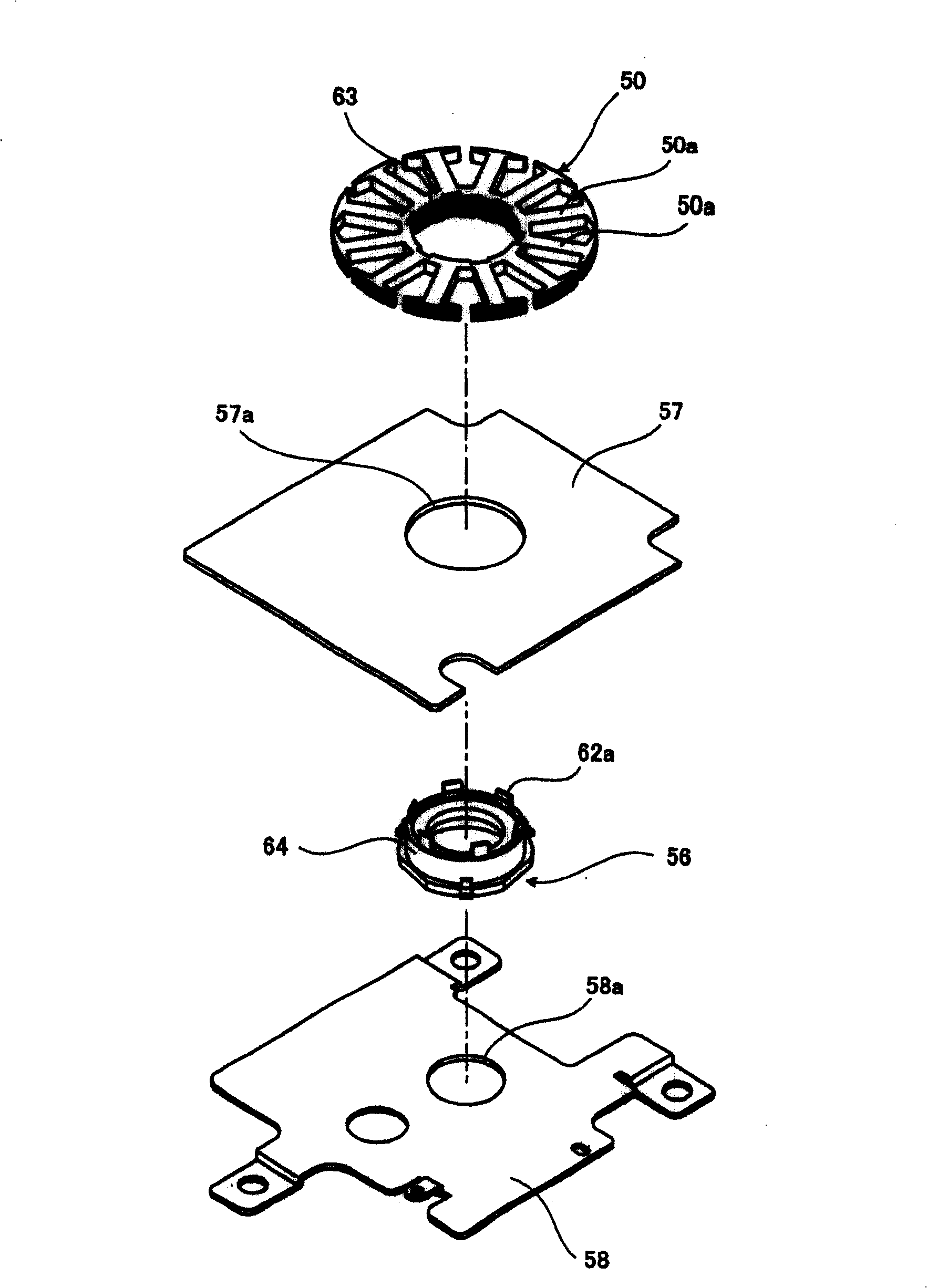
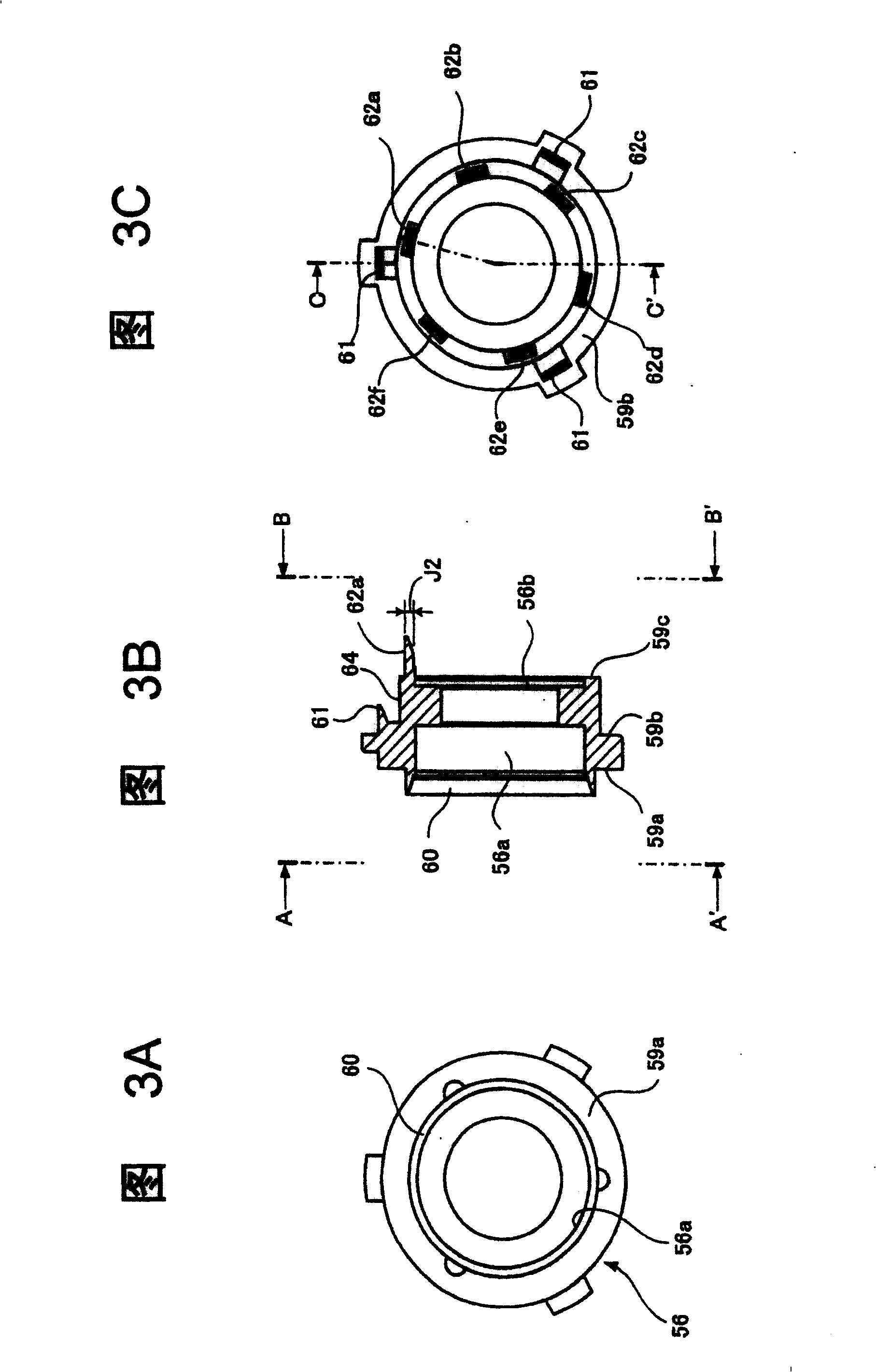
[0069] Next, various embodiments of the present invention will be described with reference to FIGS. 1 to 13A, 13B, and 13C.

[0070] (Embodiment 1)

[0071] Figure 1~ Figure 7A , Figure 7B This shows (Embodiment 1) of the present invention.

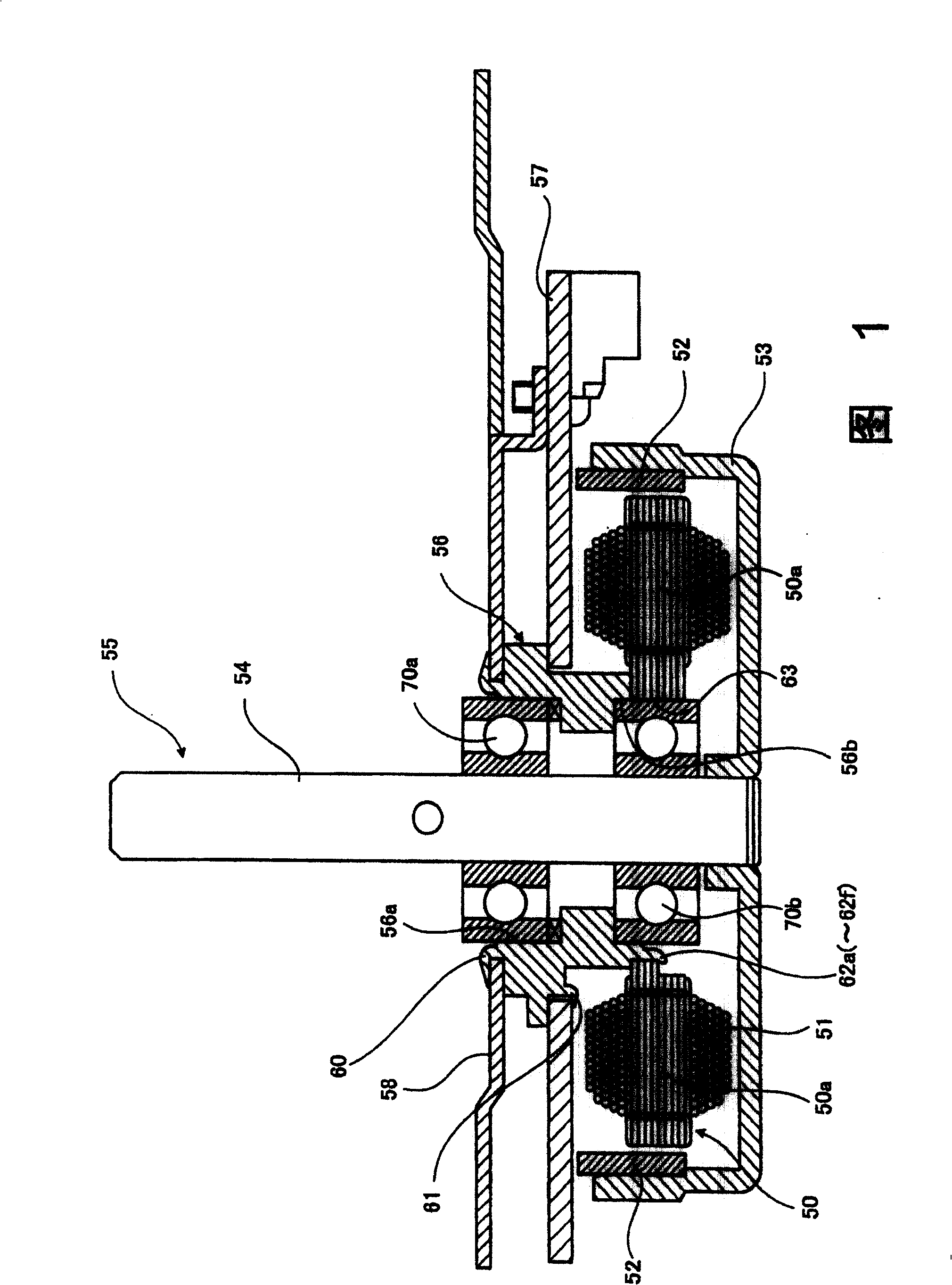
[0072] Fig. 1 shows a brushless motor of the present invention.

[0073] The stator core 50 has a plurality of salient poles 50a, and a winding 51 is wound around the salient poles 50a. The annular magnet 52 arranged to face the stator core 50 is magnetized for driving in a plurality of pieces in the circumferential direction. The ring magnet 52 is installed on the inner peripheral side of the cup-shaped rotor frame 53 . A rotating shaft 54 ​​is attached to the center of the rotor frame 53 , and the ring magnet 52 , the rotor frame 53 and the rotating shaft 54 ​​constitute a rotor 55 .

[0074] The rotating shaft 54 ​​is rotatably supported by two bearings 70a and 70b arranged at a distance from each other. The cylindrical housin...


PUM


Abstract

PROBLEM TO BE SOLVED: To provide a thin brushless motor having a small diameter in which high output is attained while saving the space by solving a matter that the winding space decreases as the diameter of a stator core decreases. SOLUTION: Since a part of the outer circumference of a bearing 70b arranged closely to the stator core 50 out of two bearings 70a and 70b for supporting the rotor 55 of a brushless motor having a circuit integrating core abuts directly against the inner circumference of the central hole 63 of the stator core 50, a thin brushless motor having a small diameter in which high output is attained while saving the space can be realized. COPYRIGHT: (C)2006,JPO&NCIPI

Description

(1) Technical field [0001] The present invention relates to a brushless motor used as a main motor for simultaneously driving various mechanisms such as copiers and laser printers. (2) Background technology [0002] In recent years, word processing products such as copiers and laser printers have increasingly demanded higher image quality, higher speed printing, and colorization. In order to achieve these requirements at the same time, the so-called tandem method, which has a photosensitive drum for each color, tends to be used. It is undeniable that changing the conventional configuration of one drum to the configuration of two drums or four drums will lead to an increase in the size of the machine. However, in order to suppress the increase in size, it is required to reduce the thickness and diameter of the main motor that drives various mechanisms. Space saving and high output. [0003] In addition, as the main motor, a brushless motor is generally used, which integrates...

Claims


Application Information

Patent Timeline
Patent Type & Authority Patents(China)
IPC IPC(8): H02K1/18H02K21/12H02K11/00
Inventor 门胁功治木村英雄
Owner MINEBEA MOTOR MFG
Learn More