Tube type vaporization device for liquefied gas for industrial use

An industrial oil and vaporization device technology, applied in the direction of combustion method, liquid fuel supply/distribution, combustion type, etc., can solve the problems of inconsistency in combustion degree, inability to solve the problems of fluid backflow, uneven heating temperature, etc., and achieve low cost and raw materials wide range of effects

Inactive Publication Date: 2008-12-17
肖杰
View PDF8 Cites 0 Cited by
  • Summary
  • Abstract
  • Description
  • Claims
  • Application Information

AI Technical Summary

Problems solved by technology

Over the years, people have been trying to use one of C5 to C10 as a raw material for liquefied gas, such as adding methanol, methyl formate, and ether to C5, and these components are all neutral poisonous substances, which have been It is expressly prohibited by the state; there is also the transportation of refined carbon five and the heating pipe side by side, using its heat to heat the carbon five to reach the saturated vapor pressure, which can be fully burned when used, but due to the uneven temperature of the heating, the degree of combustion is inconsistent, resulting in There is a large amount of liquid accumulation, and a large amount of smoke is formed during combustion, which cannot solve the problem of liquid accumulation and backflow; another kind of heating of carbon five-purpose boilers also failed due to the liquid accumulation problem

Method used


Image

  • Tube type vaporization device for liquefied gas for industrial use
  • Tube type vaporization device for liquefied gas for industrial use
  • Tube type vaporization device for liquefied gas for industrial use

Examples


Embodiment 1

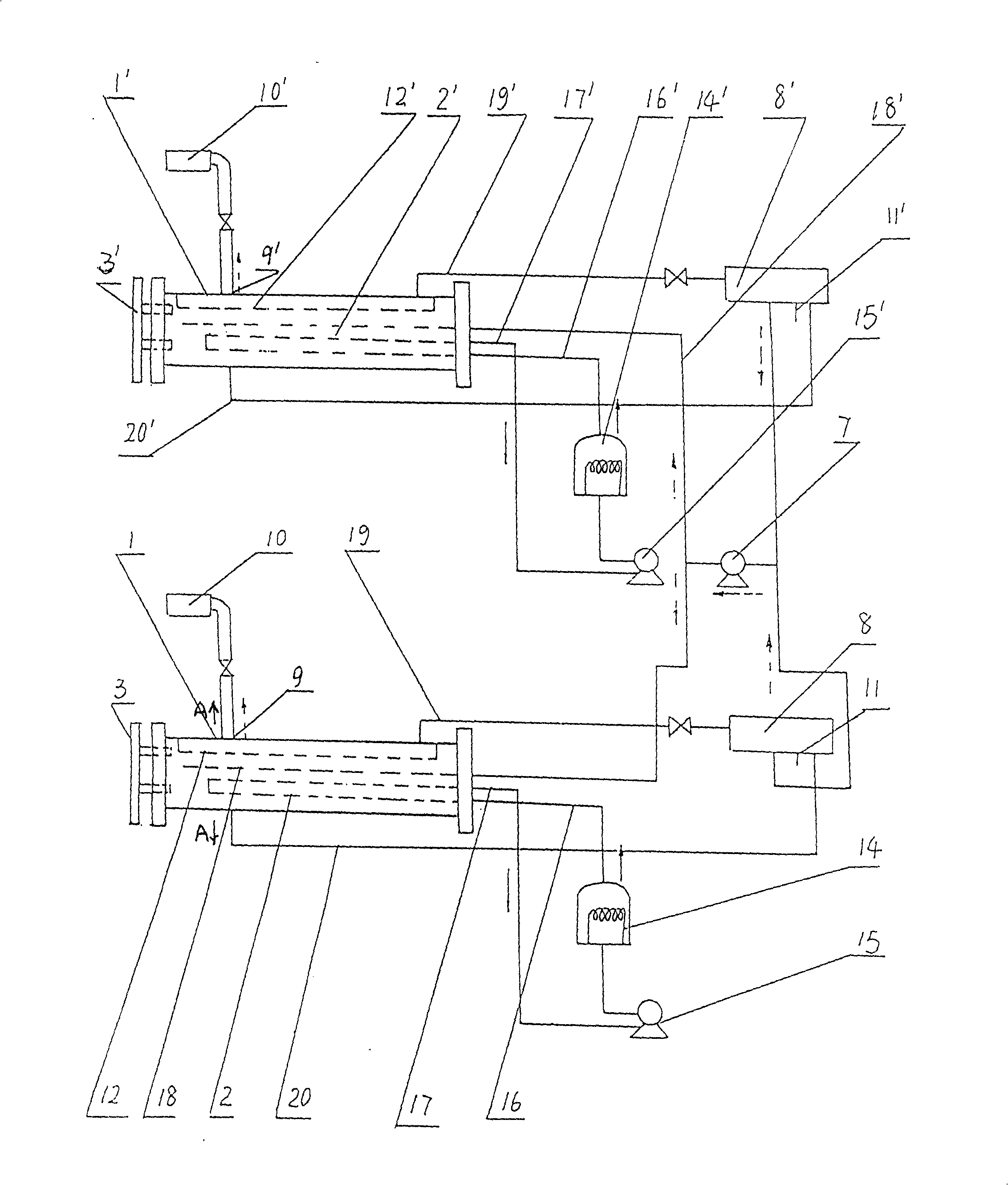
[0021] Such as figure 1 As shown, when the present invention is implemented, the vaporization part includes two sets of vaporization pipes 1, 1'; the liquid supply part includes two balance liquid storage tanks 8, 8', and an oil delivery pump 7; The combustion part includes burners 10, 10'; the heating part includes two sets of heating pots 14, 14' and hot oil pumps 15, 15' matched with the heating pots, and the heating pots in the heating part are vertical and horizontal or tubular. The hot oil output ports of the two sets of heating parts are respectively communicated with the heating medium circulation conduit inlets 4, 4' of the two sets of vaporization parts through respective heat oil pumps 15, 15' and pipelines 16, 16', and the heating medium circulation conduits 2, The outlets of 2' are respectively connected to the heating pots 14 and 14' through the respective output pipes 17 and 17' through the hot oil pumps 15 and 15' to form a heat transfer medium circulation loo...


PUM


Abstract

This invention relates to one industry oiling tube evaporation device, which comprises Evaporation part, heating part, automatic control part, burst part and liquid supply part, wherein, the evaporation tube is one hollow tube with its inside located with heating medium recycling tube; the said evaporation tube two ends are sealed with one end located with liquid level meter connected to the evaporation tube and with the other end located with heating medium entrance, exhaust mouth and gas liquid entrance; the heating medium entrance and exhaust mouth are separately connected to the heating medium recycling tube entrance and exhaust mouth.

Description

technical field [0001] The present invention relates to a device capable of keeping C5 to C10 gasified, in particular to a production device for industrial oil gas which uses C5 to C10 as raw materials in industrial production to vaporize and then combusts, especially a The utility model relates to an industrial oil-gas pipe-type vaporization device. Background technique [0002] At present, energy-saving and environment-friendly fuels are the goals pursued by human society. C5 to C10 are by-products of the petrochemical industry, and their utilization rate has been very low. Over the years, people have been trying to use one of C5 to C10 as a raw material for liquefied gas, such as adding methanol, methyl formate, and ether to C5, and these components are all neutral poisonous substances, which have been used The country expressly prohibits it; there is also the use of refined carbon five and heating pipes to be transported side by side, and the heat is used to heat the c...

Claims


Application Information

Patent Timeline
Patent Type & Authority Patents(China)
IPC IPC(8): F23K5/22F23D11/44
Inventor 肖杰陈熹
Owner 肖杰
Why Eureka
Try Eureka