Alternating current permanent-magnet water-submersible electric machine

A submersible motor and permanent magnet technology, applied to synchronous motors with stationary armatures and rotating magnets, synchronous machines, electrical components, etc., can solve the problems of complex insulation protection structure, inconvenient use, poor reliability, etc. Effects of motor stray loss, production cost reduction, and weight reduction

Inactive Publication Date: 2008-12-31
SUN YAT SEN UNIV
View PDF6 Cites 2 Cited by
  • Summary
  • Abstract
  • Description
  • Claims
  • Application Information

AI Technical Summary

Problems solved by technology

[0004] The purpose of the present invention is to solve the defects of the above-mentioned AC asynchronous submersible motor with complex insulation protection structure, poor reliability and low efficiency, and the permanent magnet DC brushless submersible motor needs to be equipped with special control equipment and DC power supply, which is troublesome to operate and not convenient enough to use Insufficiency; provide a simple and reasonable structure, good sealing and waterproof performance, easy to operate, easy to use AC permanent magnet submersible motor

Method used


Image

  • Alternating current permanent-magnet water-submersible electric machine
  • Alternating current permanent-magnet water-submersible electric machine
  • Alternating current permanent-magnet water-submersible electric machine

Examples


Embodiment 1

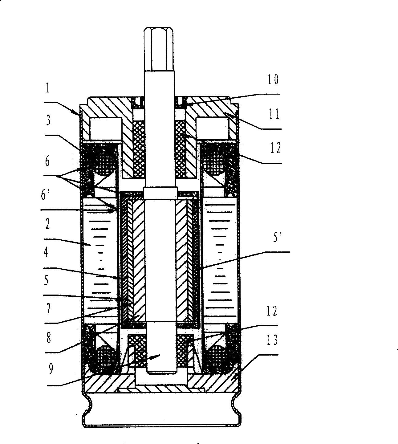
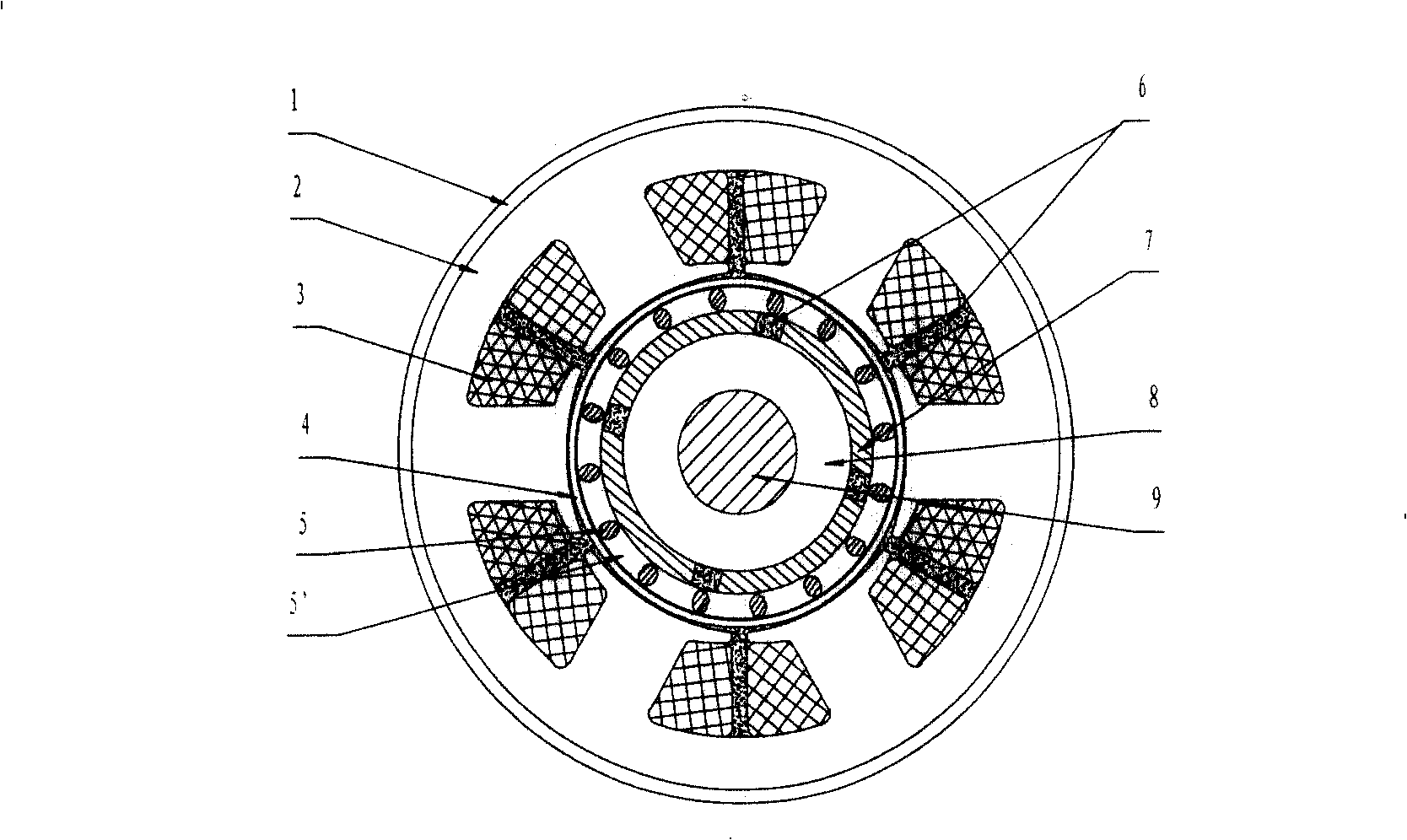
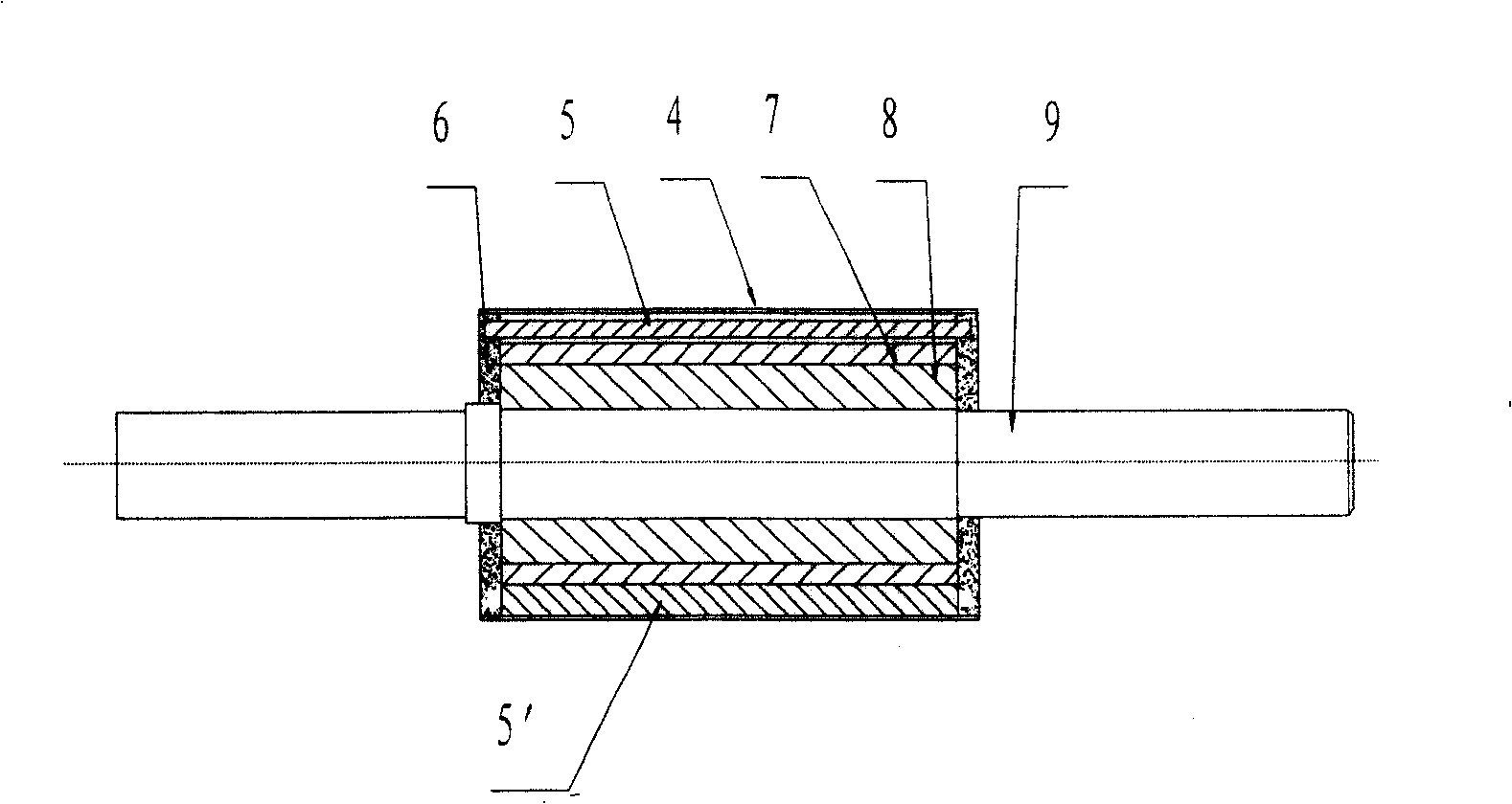
[0030] Figure 1 to Figure 4 shows the concrete structure of the present invention, by figure 1 and figure 2 It can be seen that the AC permanent magnet submersible motor has a 3-phase 4-pole structure, and the stator core has 6 teeth. The three-phase AC windings U, V, and W are respectively wound on the 6 teeth in sequential cycles, including the matingly connected stator and the rotor, the stator and the rotor are respectively integrally potted and then assembled and connected together; the stator is a concentrated winding structure, such as Figure 4 As shown, it includes casing, stator winding and iron core. The casing is connected with the stator winding and iron core by potting its internal potting material to form an integrated structure; the stator winding and iron core in the potting body are not Erosion by external liquid; the feature of potting is that a non-magnetic anti-corrosion insulating sleeve or plastic sealing material is installed on the inner circumfere...

Embodiment 2

[0032] Figure 5 Another structural form of the present invention is shown, by Figure 5 It can be seen that this embodiment is the same as Embodiment 1 except for the following structural features: the AC permanent magnet submersible motor has a single-phase 2-pole structure, and the stator core has 4 teeth, of which 2 teeth are wound with the main winding coil, and the other 2 Two teeth are used to wind the auxiliary winding coil, and the main and auxiliary windings are arranged alternately. The number of permanent magnets in the rotor is 2 pieces or an integer multiple of 2 pieces.

Embodiment 3

[0034] Figure 6 Another structural form of the present invention is shown, by Figure 6 It can be seen that this embodiment is the same as Embodiment 1 except for the following structural features: this AC permanent magnet submersible motor has a 3-phase 2-pole structure, its stator core has 3 teeth, and the three-phase windings U, V, W rotate according to the motor. Direction, sequentially wound on 3 teeth, the number of permanent magnets of the rotor is 2 pieces or an integer multiple of 2 pieces.


PUM


Abstract

The submersible motor includes connected stator and rotor cooperated to each other. Being encapsulated respectively, stator and rotor are connected through assembling procedure. The stator is in concentrated winding structure. The rotor contains cage type starting winding and permanent magnet. There are uneven air gap between stator teeth and rotor. Using integral encapsulating technique, the invention treats motor so as to obtain features: simplifying waterproof insulation structure, eliminating mechanical loss of attrition caused by waterproof mechanical seal, reducing size, saving material, improving runnability, and raising reliability and efficiency of insulation of submersible motor.

Description

technical field [0001] The invention relates to a permanent magnet motor, in particular to an AC permanent magnet submersible motor. Background technique [0002] The submersible pumps widely used in the market are driven by AC asynchronous submersible motors and are mainly used to extract groundwater. The insulation and waterproof structure of AC asynchronous submersible motors basically adopts liquid-filled or dry-type mechanical seals. Due to the complex waterproof structure and large mechanical loss, the submersible motor has large volume, low efficiency, poor reliability of waterproof insulation, and even water pollution (oil-filled type) ). Especially for small AC asynchronous submersible motors, due to the large amount of active power consumed by its rotor excitation loss and waterproof mechanical seal, the loss accounts for an excessively large proportion of its input power, making it difficult to improve its efficiency. The national standard GB / T2818-2002 stipulat...

Claims


Application Information

Patent Timeline
Patent Type & Authority Patents(China)
IPC IPC(8): H02K21/46H02K21/12H02K5/132
Inventor 周毅人叶蓓英陈鸣王飞赵彦郑寿生王茹晖
Owner SUN YAT SEN UNIV
Why Eureka
Try Eureka