Stepping motor and drive device
A technology of stepping motors and magnets, applied in the direction of motor generator control, electromechanical devices, electrical components, etc., can solve problems such as difficult construction
- Summary
- Abstract
- Description
- Claims
- Application Information
AI Technical Summary
Problems solved by technology
Method used
Image
Examples
Embodiment 1
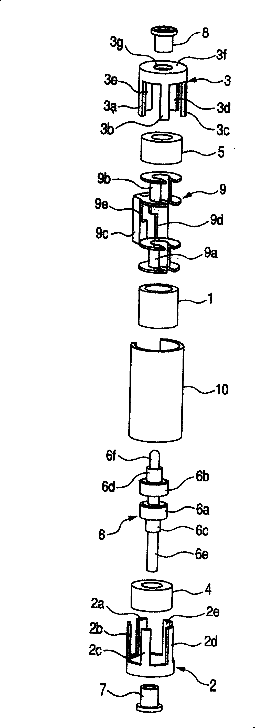
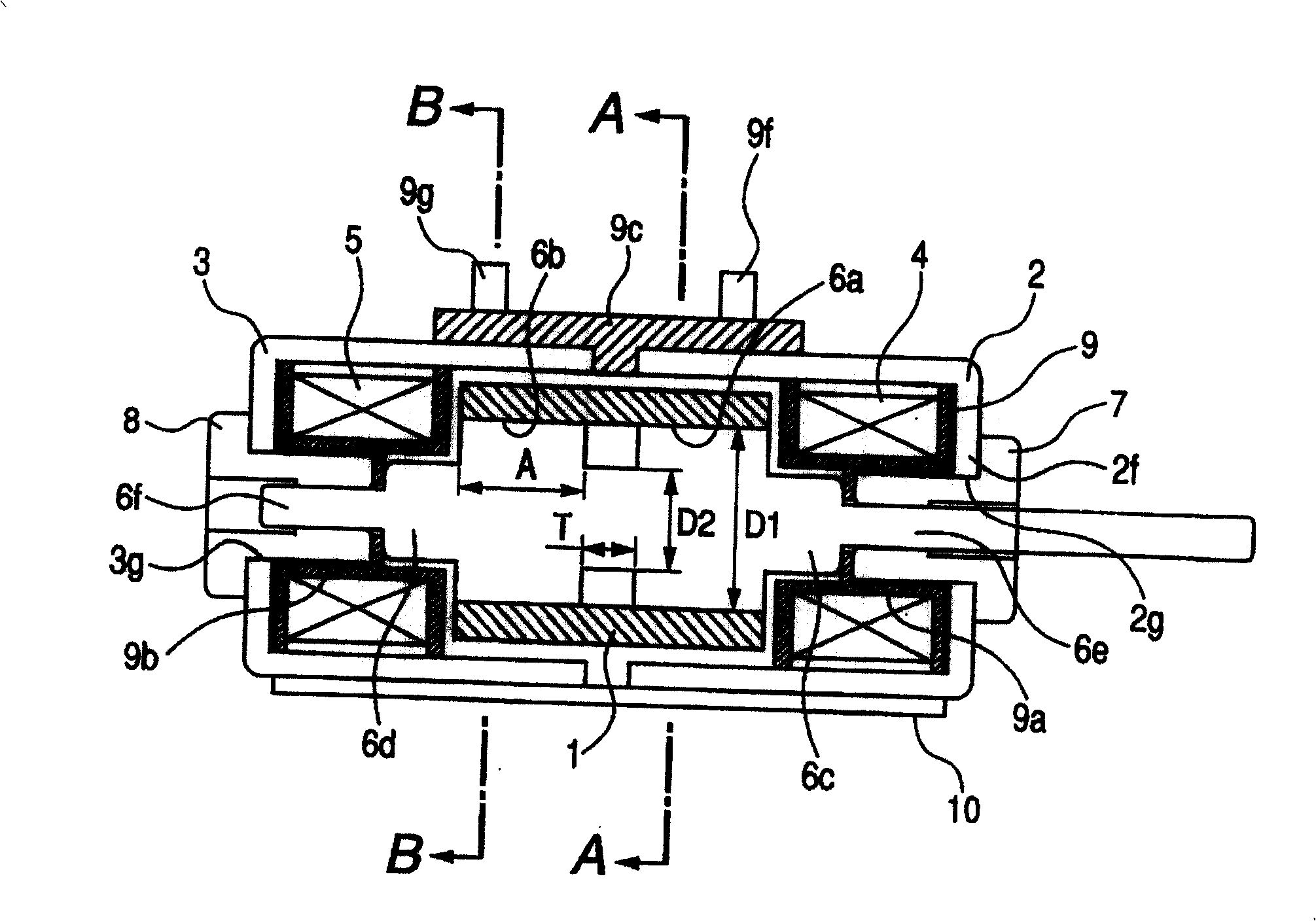
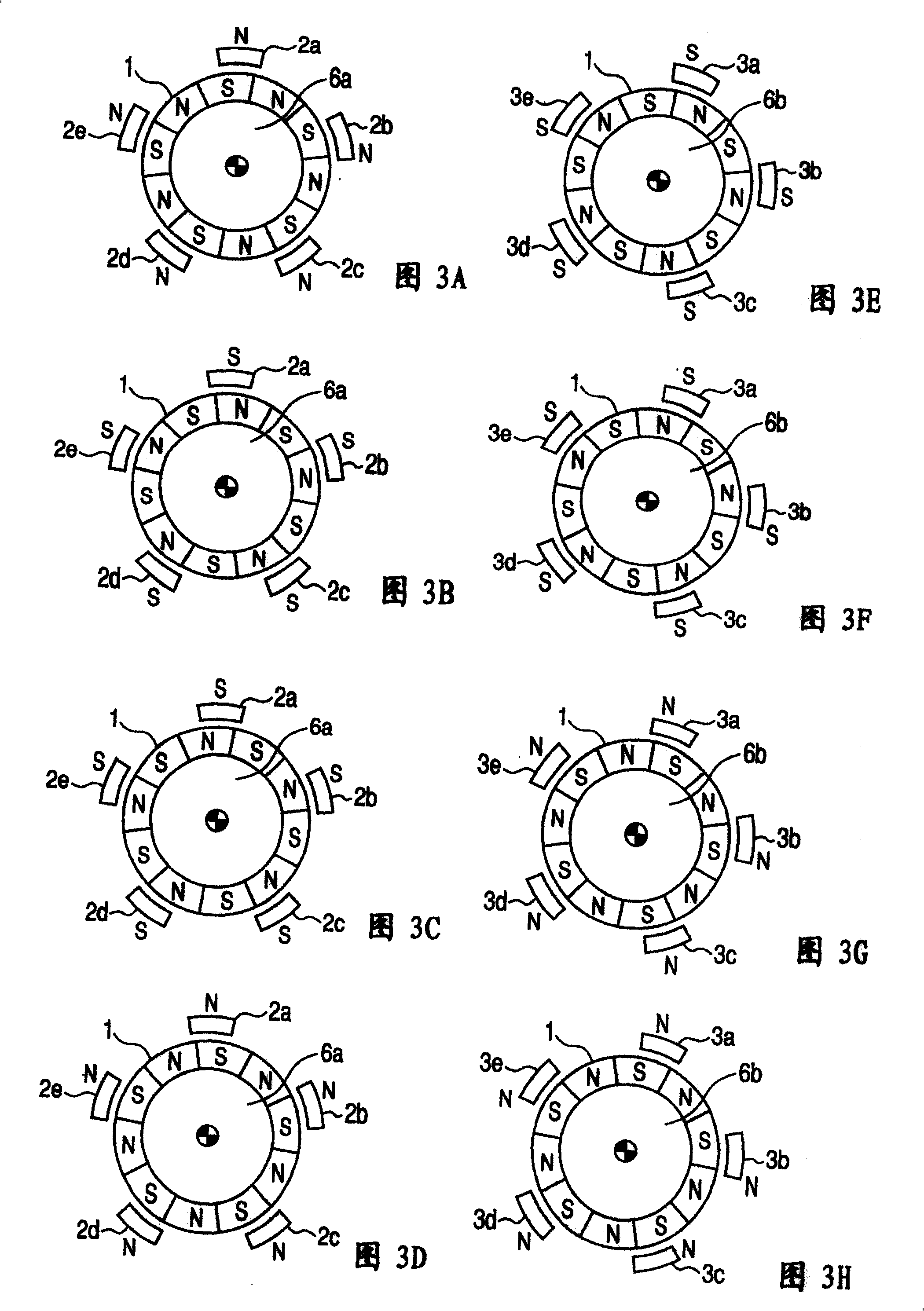
[0062] figure 1 , 2 3A to 3H are diagrams of Embodiment 1 of the present invention. in, figure 1 It is an exploded perspective view of a stepping motor. figure 2 yes figure 1 Axial cross-sectional view of the stepper motor shown after assembly.
[0063] exist figure 1 and figure 2 Among them, 1 is a cylindrical magnet whose outer peripheral surface is divided into n parts along the circumferential direction (n=10 in this embodiment 1), and these parts are alternately magnetized into S poles and N poles. 2 is the first stator made of soft magnetic material, which is composed of an outer cylinder and an annular top plate 2f with a hole 2g opened in the center. The outer cylinder of the first stator 2 is formed with first outer magnetic pole portions 2a, 2b, 2c, 2d, and 2e protruding in the axial direction at the front end thereof, and the distance between the first outer magnetic pole portions 2a to 2e in the circumferential direction is It is 720 / n degrees (72 degre...
Embodiment 2
[0086] Figure 4~7 and Figures 8A-8D It is a figure which shows Example 2 of this invention. in, Figure 4 It is an exploded perspective view of the stepping motor of the second embodiment. Figure 5 yes Figure 4 Axial cross-sectional view of the stepper motor shown after assembly. Figure 6A , 6B yes Figure 4 The structural diagram showing the details of the constituent parts of the stepping motor, that is, the coil bobbin. Figure 7 yes Figure 5 7-7 section view in.
[0087] In these figures, 11 is a cylindrical magnet, and its outer peripheral surface is divided into integer multiples of 4 at intervals along the circumferential direction, that is, 4×n (n is an integer, and n=4 in the present embodiment 2, so the number of divisions is 16) parts, these parts are alternately excited as S pole and N pole. 14 is a cylindrical first coil, and 15 is a cylindrical second coil. The two coils 14 and 15 have their centers aligned with the center of the magnet 11, and ar...
Embodiment 3
[0114] Figure 9 It is an exploded perspective view showing a stepping motor as a driving device according to an embodiment of the present invention. Figure 10 It is a plan view showing an FPC incorporating a stepping motor. Figure 11 It is a cross-sectional view along the rotation axis of the assembled stepping motor.
[0115] Figure 9 to Figure 11 Among them, the stepping motor has a magnet 21, a first stator 22, a second stator 23, a first coil 24, a second coil 25, a rotating shaft 26, a first bearing 27, a second bearing 28, a first bobbin 29, a first 2 coil bobbin 30, FPC31.
[0116] The magnet 21 is cylindrical and has a magnetized portion. The magnetized portion divides the outer peripheral surface of the magnet 21 into N (10 in this embodiment) parts in the circumferential direction, and each part is alternately magnetized into S poles and N poles. Extremely made.
[0117] The first stator 22 is made of a soft magnetic material, and has an outer cylinder porti...
PUM
 Abstract
Description
Claims
Application Information
 - R&D
- Intellectual Property
- Life Sciences
- Materials
- Tech Scout
- Unparalleled Data Quality
- Higher Quality Content
- 60% Fewer Hallucinations
Browse by: Latest US Patents, China's latest patents, Technical Efficacy Thesaurus, Application Domain, Technology Topic, Popular Technical Reports.
© 2025 PatSnap. All rights reserved.Legal|Privacy policy|Modern Slavery Act Transparency Statement|Sitemap|About US| Contact US: help@patsnap.com


