
Anti-vibration system and device for bicycle steering tube

A steering rod and bicycle technology, applied in bicycle accessories, steering mechanism, transportation and packaging, etc., to avoid injuries and increase comfort

Inactive Publication Date: 2009-01-14
游炎征
View PDF6 Cites 0 Cited by
  • Summary
  • Abstract
  • Description
  • Claims
  • Application Information

AI Technical Summary

Problems solved by technology

The reason is that in the prior art, the handle e of the bicycle and the guide rod f of the car body a are fixedly integrated, and the rebound impact force caused by the bicycle traveling on an uneven road surface will be transferred to the handle e, and then to the cyclist's wrists, elbows, shoulders and brain

Method used


Image

  • Anti-vibration system and device for bicycle steering tube
  • Anti-vibration system and device for bicycle steering tube
  • Anti-vibration system and device for bicycle steering tube

Examples


Embodiment Construction

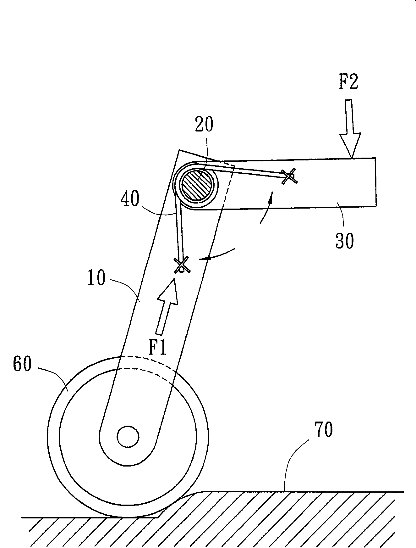
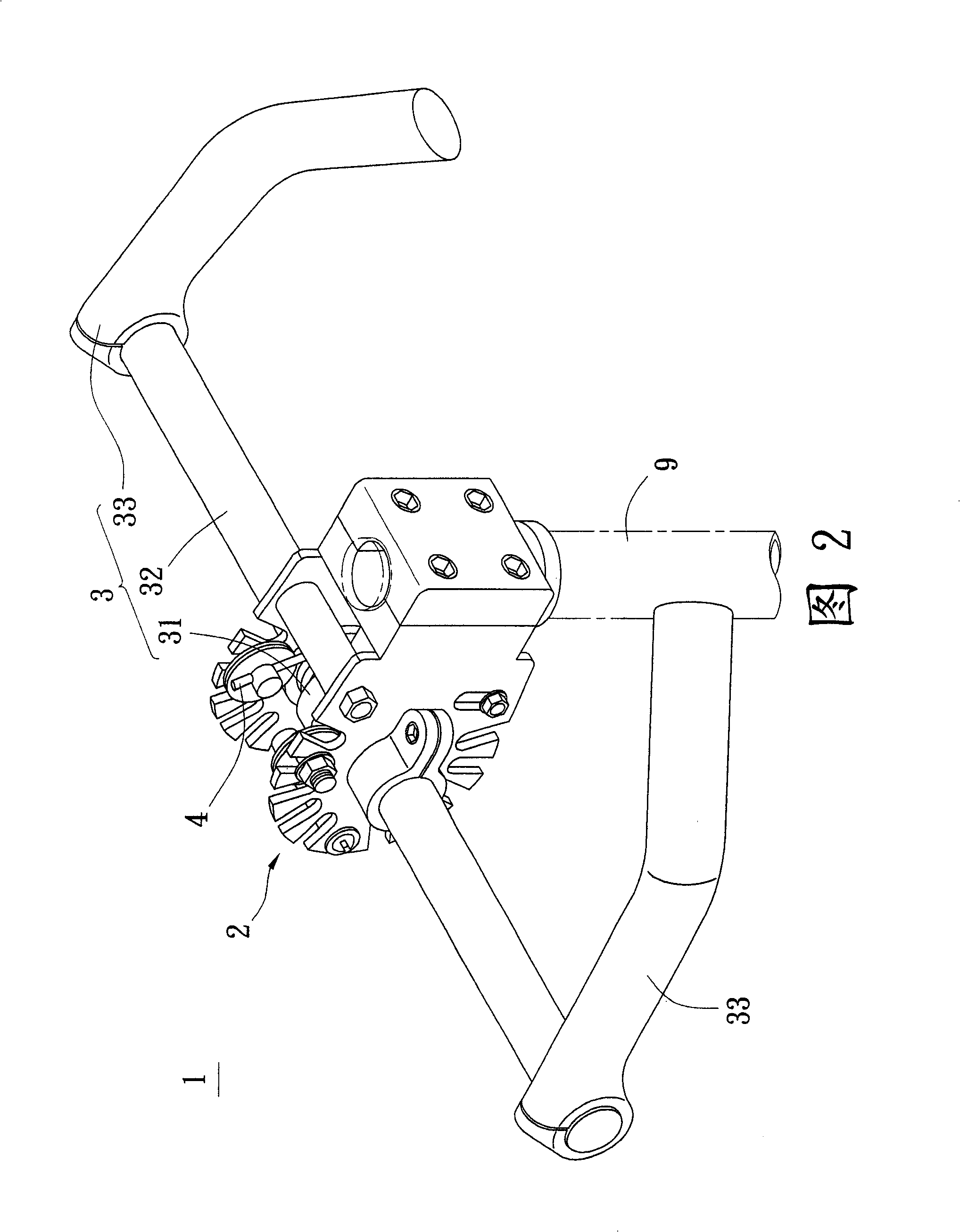
[0049] see figure 1 As shown, it shows the working principle of the bicycle steering rod shock absorber of the present invention. When the wheels 60 meet the ground 70 with depressions or protrusions during driving, the vehicle body 10 bounces instantly and bounces upwards to generate a force F1. The shock-absorbing device of the bicycle direction bar of the present invention is to make the direction bar be combined on the vehicle body 10 in the state of twisting and rolling, like figure 1 The rolling shaft 20 in the middle; the handle of the present invention is connected on the direction rod at an angle, so it forms a swing arm 30 for the direction rod (or rolling shaft 20), and makes the swing arm 30 operate in a lever manner to twist the direction rod and the present invention is provided with a torsion spring device 40, erected in the middle of the direction bar and the car body, because the handle is fixedly combined on the direction bar, so the fixing of the torsion sp...


PUM


Abstract

A vibration damping system for the handlebar of bicycle features that the handlebar is linked to the frame of bicycle in a rolling mode, a pair of handle is connected to its transverse bar by a certain angle to form radial arms, and a torsional spring unit is installed between the handlebar and frame.

Description

technical field [0001] The invention relates to a shock absorber for a steering rod of a bicycle. Background technique [0002] Bicycle is a very convenient means of transportation, but also a tool for exercise and entertainment; however, when the bicycle is running on uneven roads, it will inevitably cause rebound and jumping impact, which makes people feel uncomfortable and even causes damage to the human body. [0003] In order to avoid the above-mentioned vibrations causing human injury, the industry has indeed made great efforts to continuously improve, for example: 1. A compression shock absorber is installed at the front fork. 2. Install an elastic device on the seat cushion. 3. Add spring devices at other parts of the car body. As shown in Figure 21, the shock absorber of the bicycle in the prior art includes: a spring type or hydraulic shock absorber d is arranged under the front fork c; an elastic device is arranged on the seat cushion part g, or the seat cushion...

Claims


Application Information

Patent Timeline
Patent Type & Authority Patents(China)
IPC IPC(8): B62K21/14
Inventor 游炎徵
Owner 游炎征
Learn More