Gas-solid fluidized coupling equipment and coupling method for particle mixing-classifying by utilizing same

A coupling equipment and fluidization technology, applied in the direction of chemical instruments and methods, chemical/physical processes, etc., to achieve the effects of compact equipment structure, improved classification efficiency, and reduced fluidization air volume

Active Publication Date: 2009-01-21
CHINA UNIV OF PETROLEUM (BEIJING)
View PDF6 Cites 2 Cited by
  • Summary
  • Abstract
  • Description
  • Claims
  • Application Information

AI Technical Summary

Problems solved by technology

In a similar process, how to ensure good mixing of gas, solid, and solid to efficiently complete the processing steps such as reaction and heat exchange, and at the same time efficiently classify the mixed particles has become a bottleneck problem restricting the application of coupling technology.

Method used


Image

  • Gas-solid fluidized coupling equipment and coupling method for particle mixing-classifying by utilizing same
  • Gas-solid fluidized coupling equipment and coupling method for particle mixing-classifying by utilizing same
  • Gas-solid fluidized coupling equipment and coupling method for particle mixing-classifying by utilizing same

Examples


Embodiment 1

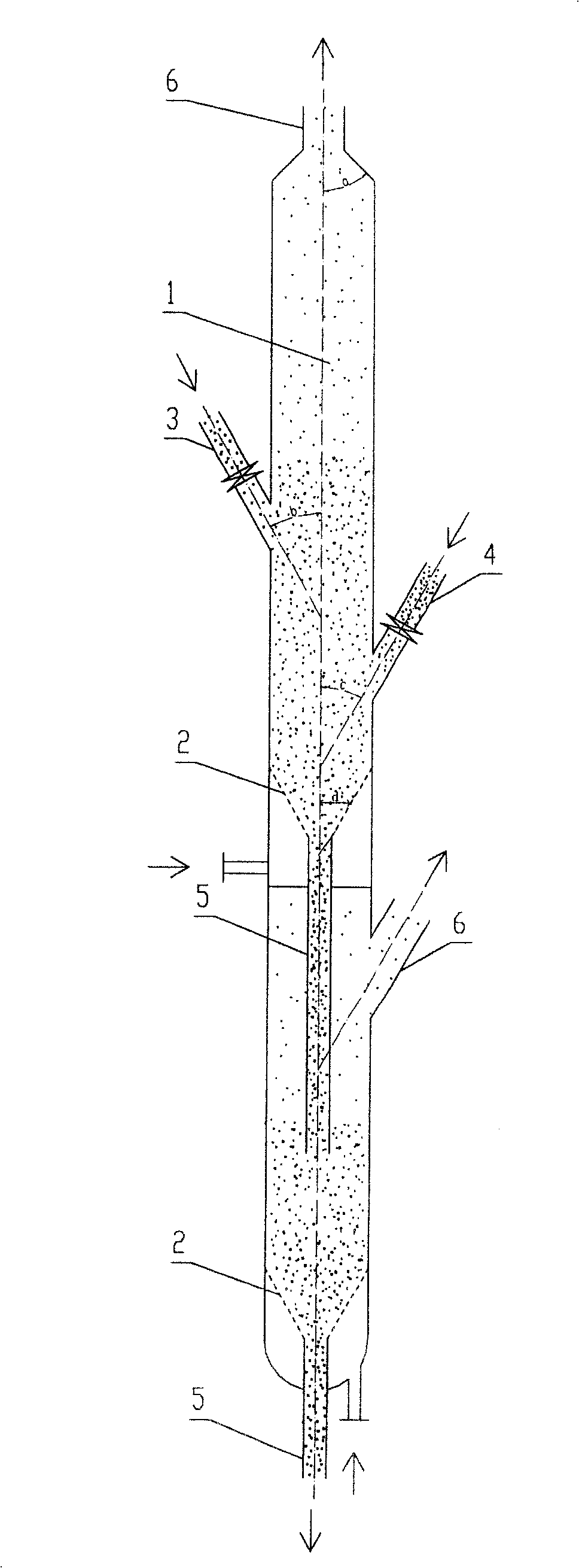
[0035] See figure 1 As shown, it is a structural schematic diagram of a specific embodiment 1 of the gas-solid fluidization coupling device of the present invention, two gas-solid fluidized bed bodies 1 form an integrated two-stage fluidized bed body in series, and the entire two-stage gas-solid fluidized bed body The solid fluidized bed 1 is a vertical cylinder, the top of the first-stage fluidized bed is a tapered diameter-reducing structure, the upper part forms the small particle outlet pipe 6 of this stage, and the large particle inlet pipe 3 is respectively arranged on the cylinder wall And the small particle inlet pipe 4, the distance between the large particle inlet pipe 3 and the top tapered large port is greater than 1000mm, and the gas distribution plate 2 is arranged in an inverted cone shape in the cylinder body, and the upper part closes the lower end of the fluidized bed body 1, and is separated from the small particle The distance of inlet pipe 4 is at least 20...

Embodiment 2

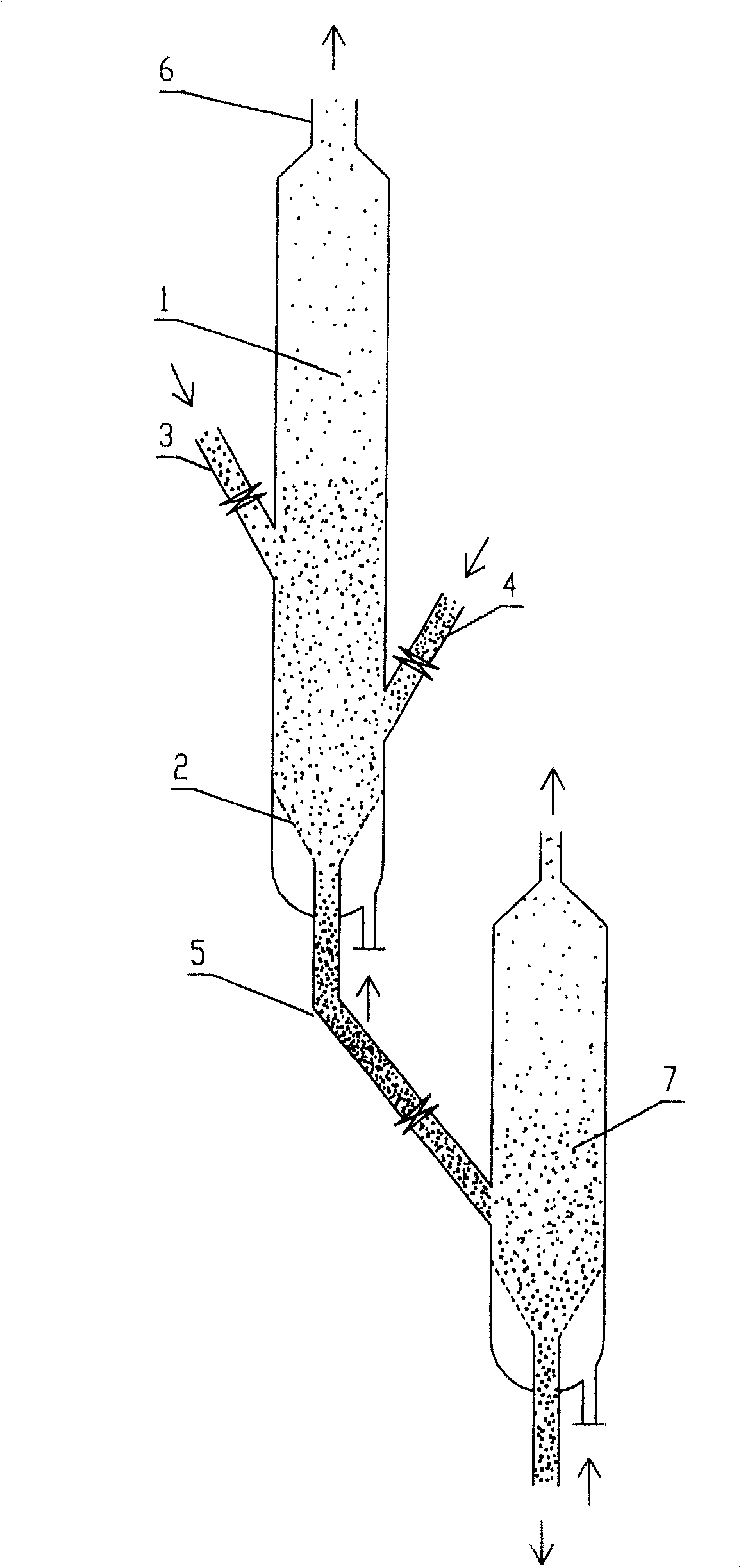
[0044] figure 2 It is the front view of the second embodiment of the present invention, as can be seen, with figure 1 The difference is that each fluidized bed body is an independent single-stage gas-solid fluidized bed body, and the large particle outlet pipe 5 of the first-stage fluidized bed body 1 communicates with the side wall of the second-stage fluidized bed body 7 to form the second stage. Secondary particle inlet tube. According to the needs of classification accuracy and operation, it can be connected in series in this way to adapt to different venues and adopt more flexible operations.

[0045] Similarly, a gas distributor 19 may also be arranged in the fluidized bed body.

Embodiment 3

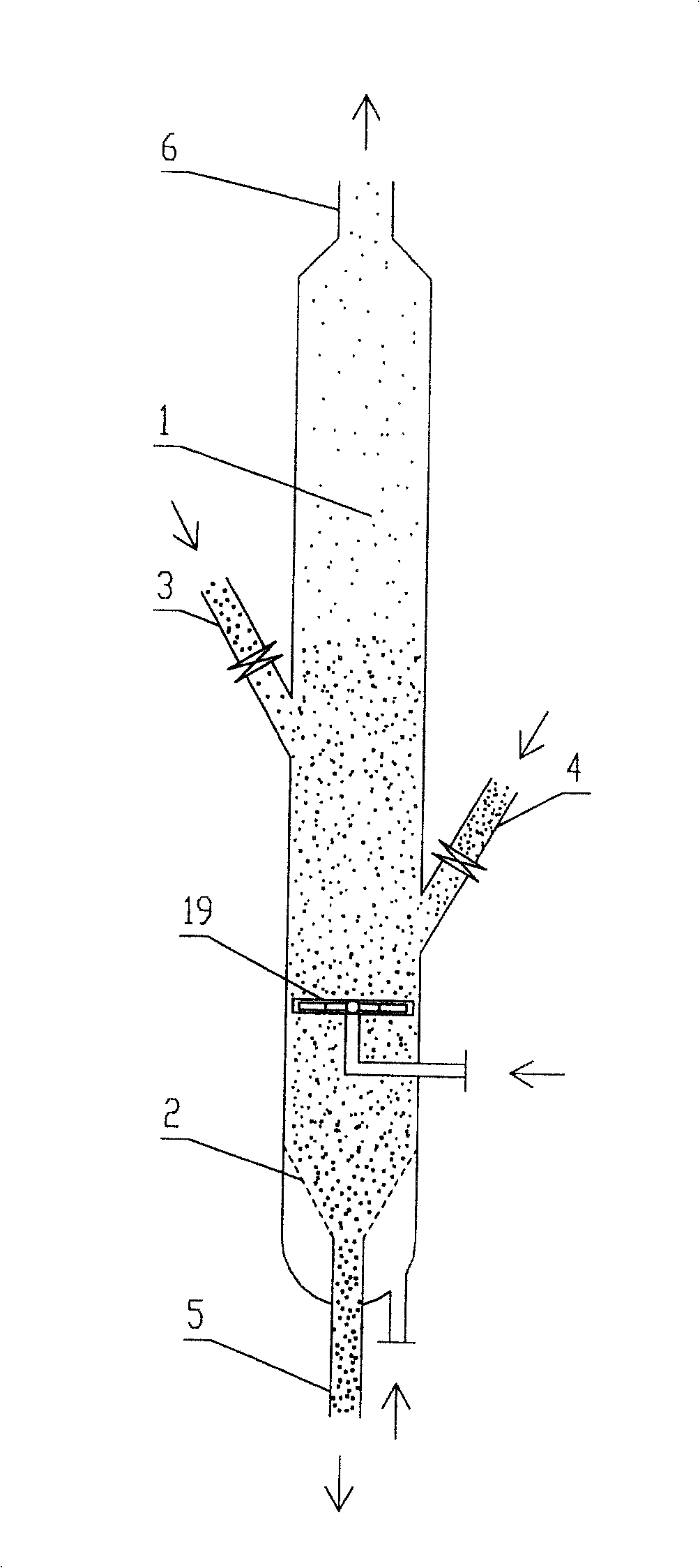
[0047] image 3 It is the front view of the third embodiment of the present invention. A gas distributor 19 is added in the dense phase between the small particle inlet pipe 4 and the gas distribution plate 2. According to the site, operation, classification requirements, etc., the fluidized bed body is both But the single-stage (single-stage) formula can be used alone, and can also be combined into multi-stage (or multi-stage) according to the mode of embodiment one and embodiment two.

[0048] When implemented in combination according to the method of Example 2, the amount of gas entering through the gas distribution plate 2 is smaller than that of the solution of Example 1, and the fluidized bed containing both large and small particles is utilized at a lower gas velocity, and the bottom of the dense bed Can form almost pure large particle layer, can form the phenomenon of mixed particle layer on the large particle layer, form almost pure large particle layer between distri...


PUM


Abstract

The present invention provides a gas-solids fluidization coupling equipment. It at least includes an one-stage gas-solids fluidized bed body, said fluidized bed body is a vertically-placed cylinder body. Said invention also provides the concrete structure of said gas-solids fluidized bed body. Besides, said invention also provides a coupling method capable of utilizing said equipment to implement multistage mixing, heat exchange, reaction and classification of granules with large difference.

Description

technical field [0001] The invention relates to a gas-solid fluidization coupling device and a coupling method for particle mixing and grading by using the device, especially a method that can completely mix particles of different sizes to facilitate the completion of processing steps such as reaction and heat exchange. , and the coupling device and method that can classify the mixed particles again can be widely used in the fields of petroleum refining, chemical industry, metallurgy, agriculture and the like that involve the treatment of granular materials. Background technique [0002] At present, granular materials are widely used in many industries, such as solid catalysts widely used in petroleum refining or other chemical industries, minerals in the mining industry, and grains in agriculture. Particle size and particle size distribution have certain requirements, and particle size distribution often has a great or even crucial impact on the process or material performa...

Claims


Application Information

Patent Timeline
Patent Type & Authority Patents(China)
IPC IPC(8): B01J8/24
Inventor 卢春喜张树青高金森徐春明时铭显
Owner CHINA UNIV OF PETROLEUM (BEIJING)
Why Eureka
Try Eureka