Pneumatic control localizer

A pneumatic control and positioner technology, applied in automatic control devices, positioning devices, manufacturing tools, etc., can solve the problems of large operation space, floating positioning coordinates, low positioning accuracy, etc., and achieve stable positioning coordinates and assembly speed. And the effect of improving product quality and simplifying the control process

Active Publication Date: 2009-01-21
CHENGDU AIRCRAFT INDUSTRY GROUP
View PDF5 Cites 0 Cited by
  • Summary
  • Abstract
  • Description
  • Claims
  • Application Information

AI Technical Summary

Problems solved by technology

[0003] The object of the present invention aims at the deficiencies of the above-mentioned prior art, and provides a pneumatically controlled locator composed of pneumatic control technology combined with mechanical control technology to solve the problems of floating positioning coordinates, unstable positioning, and low positioning accuracy in the prior art. The problem of taking up a large operating space

Method used


Image

  • Pneumatic control localizer
  • Pneumatic control localizer
  • Pneumatic control localizer

Examples


Embodiment Construction

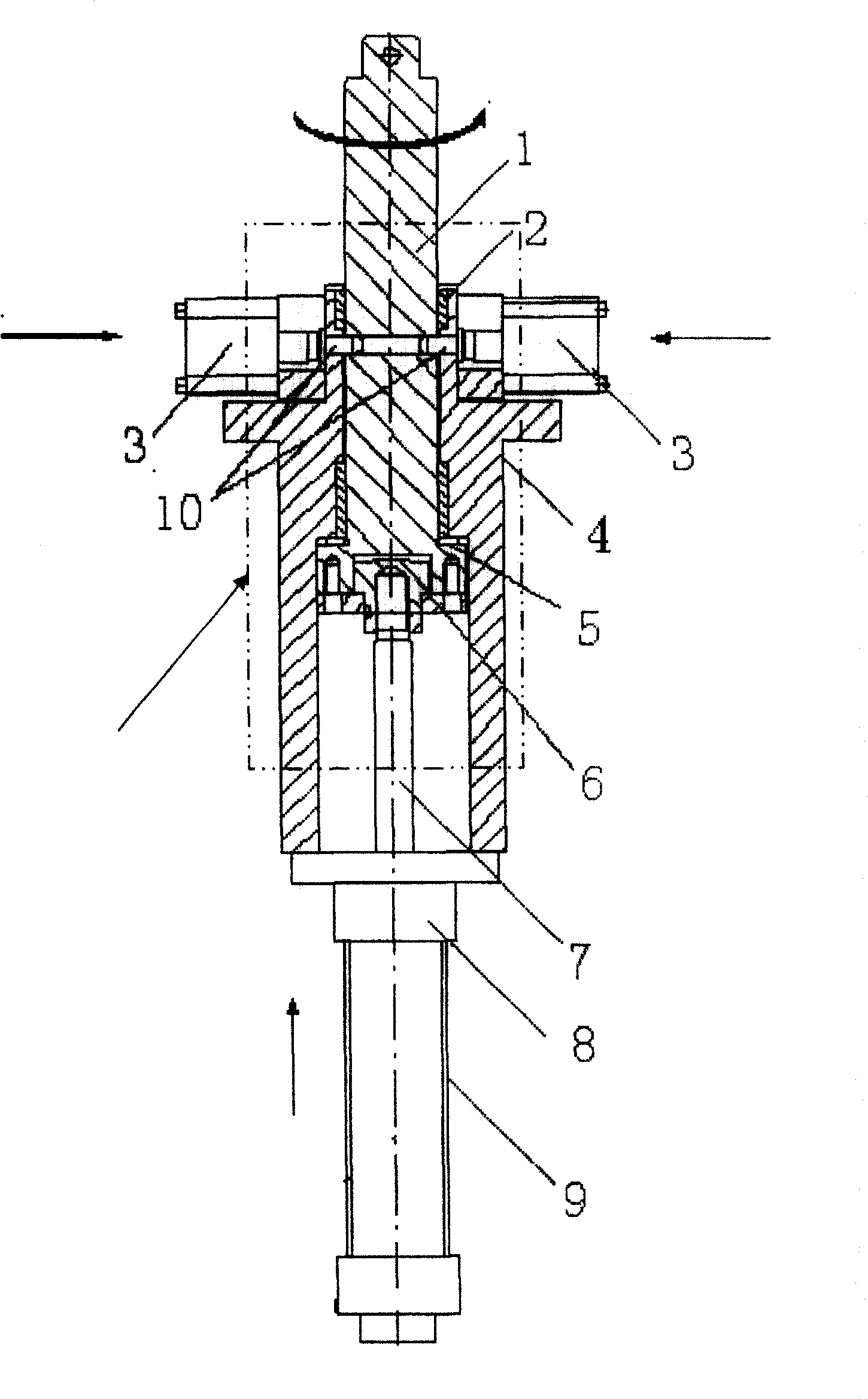
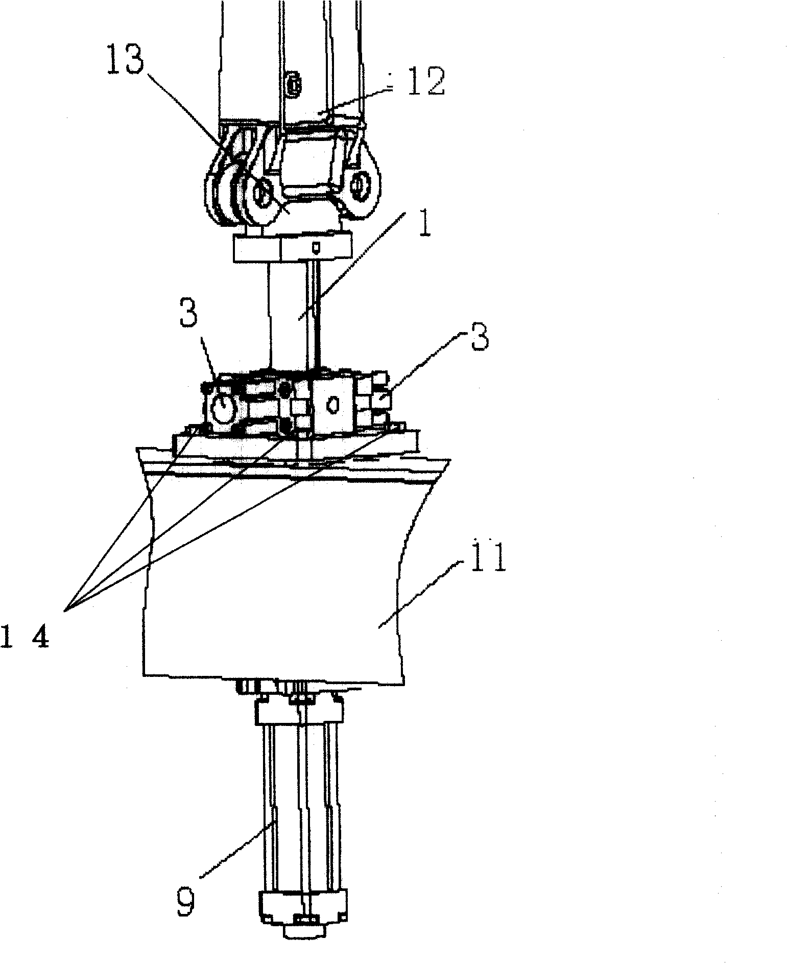
[0011] see figure 1 , the mechanical positioning control seat body 4 is a cylindrical cylinder shaped on steps and step holes. The positioning rod 1 is slidably fitted in the stepped hole, and can generate sliding movement under the action of the pneumatic connecting rod 7 . On the connecting rod 7 connected to the lower end of the positioning rod 1, a floating head 6 and an initial positioning gasket 5 that makes the end of the positioning rod reach the initial positioning position are connected. The connecting rod 7 pushes the positioning rod 1 for axial positioning movement through the connected axial cylinder 9, and constrains the positioning rod 1 axially in the direction of the arrow. The tangential cylinders 3 respectively installed on both sides of the mechanical positioning seat body 4 push the bullet pin 10, and the positioning rod 1 and the mechanical positioning control body seat 4 are aligned to the holes, so as to realize the tangential constraint along the dir...


PUM


Abstract

The present invention discloses an aerodynamic control localizer comprising a mechanical locating controller, a locating rod moving through the mechanical locating controller and electric and aerodynamic parts. The present invention is characterized in that the lower end of the locating rod which is equipped and can slide in the mechanical locating controller is connected with a floating head connected with a cylinder link lever and an initiative locating shim which makes the locating rod end reach the initiative locating position; the cylinder link lever drives the locating rod move axially by the connected axial cylinder; with a connected bullet pin, tangential cylinders equipped on both sides of the locating rod implement hole-to-hole location of the locating rod and the mechanical locating controller base to realize tangential location to make the locating device reach the final coordinate position. The localizer is characterized by simple flexible accurate structure, stable locating coordinates and conveniently controlled automatic operation. The present invention will thoroughly change and overcome the defect of the traditional screw type localizer that the locating accuracy is not high, location is not stable and the production cycle is long. Moreover, the volume is decreased by about one third compared with the tradition al screw type localizer.

Description

technical field [0001] The invention relates to a positioning device used in the design and manufacture of an aircraft process assembly frame. Background technique [0002] In the prior art, the positioning devices widely used in aircraft process assembly jigs basically adopt various models stipulated in the "Aircraft Assembly Fixture Components" HB597~HB602 aviation industry standards issued by the Ministry of Aerospace Industry of China in 1997. Screw type positioner. The positioning form of the screw positioner specified in the aviation industry standard is image 3 Traditional manual mechanical positioning shown. The base material is HT20-40 or HT15-33 cast iron, and the tolerance H9 / h6 surface roughness matched with the screw is not reasonable. . The screw rod and the seat are matched by a rack, and the gap between the teeth can only be improved and compensated by the operator's experience and feeling. Therefore, it often causes the positioning coordinates to float,...

Claims


Application Information

Patent Timeline
Patent Type & Authority Patents(China)
IPC IPC(8): B23Q15/22B23Q3/18
Inventor 孙海龙李东明
Owner CHENGDU AIRCRAFT INDUSTRY GROUP
Why Eureka
Try Eureka