Sieve tube with flow adjuster
A control device and screen pipe technology, which is applied in the direction of production fluid, wellbore/well components, earthwork drilling and production, etc., can solve the problems of complicated operation, inability to meet the control of flow state in different sections, and difficult separation operation, so as to achieve simple and convenient operation Effect
- Summary
- Abstract
- Description
- Claims
- Application Information
AI Technical Summary
Problems solved by technology
Method used
Image

Examples
Embodiment 1
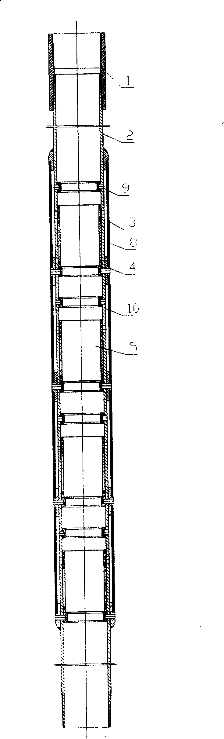
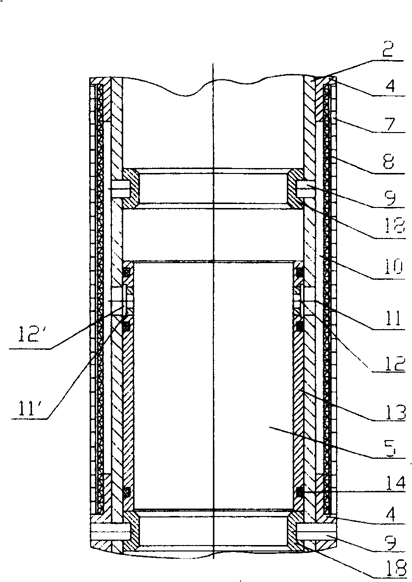
[0046] Such as figure 1 , 2 As shown, the present invention includes a screen joint 1, a base pipe 2 and a sand control section 3, an isolation ring 4, a collecting cavity 10, a flow control device 5, etc. The base pipe 2 is provided with a collecting hole 11 on the pipe wall. Hole 11 communicates with collecting cavity 10 and is used to collect formation fluid from the outer side of the base pipe to its inner side, or to disperse the injected fluid from the inner side of the base pipe to its outer side; the screen pipe is equipped with a flow control device 5.
[0047] More than one isolation ring 4 is provided on the base pipe 2 of the screen, which divides the screen into more than one isolation unit. The outside of the base pipe of each isolation unit is inside the sand control section 3 between the adjacent support rings 4 With sand control layer 8. A protective cover 7 is sometimes provided outside the sand control layer 8. The isolation ring 4, the outer wall of the base p...
Embodiment 2
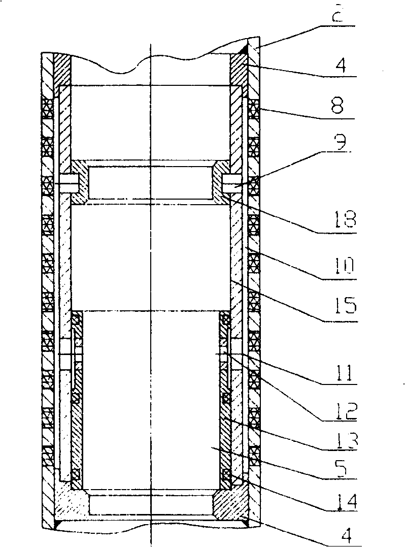
[0053] Such as image 3 As shown, the difference between this embodiment and the above-mentioned embodiment 1 is that the sand control layer 8 in this embodiment is directly arranged on the tube body of the base pipe 2, such as slotted screens, inlaid metal fiber block screens, etc. Sieve. When the flow control device 5 is installed on this type of screen, it is necessary to set a center tube 15 and an isolation ring 4 inside the screen. The outer wall of the center tube 15, the inner wall of the base pipe 2 of the screen, and the isolation ring at both ends of the center tube 15 4 A collecting cavity 10 is formed, and the collecting hole 11 is opened on the central pipe 15. The flow control device 5 includes a sliding sleeve 13, a throttle nozzle 12, a sealing ring 14 and a limit ring 18, etc., all of which are arranged inside the center tube 15.
[0054] The isolation ring 4 is a metal ring, a rubber ring or a plastic ring, and is fixed to the inner wall of the base pipe 2 by we...
Embodiment 3
[0058] Such as Figure 4 As shown, the difference between this embodiment and Embodiment 1 is that the flow control device 5 is actually a sliding sleeve switch. There is no throttle nozzle on the sliding sleeve 13 and the sliding sleeve 13 can be installed on the inner wall of the base pipe 2 along the pipe. The body slides axially. Through the movement of the sliding sleeve 13, the open and closed state of the collecting hole 11 opened on the base pipe 2 is changed to realize the control of the fluid. When the sliding sleeve 13 is closed, the sealing ring 14 provided on the outer wall of the sliding sleeve 13 plays a sealing role.
[0059] The flow control device 5 can also be a rotary sliding sleeve switch. The sliding sleeve 13 can be rotated in the base pipe 2 to make the opening on the sliding sleeve 13 communicate with or close the collecting hole 11 through rotation. The limiting device may be a protrusion fixed on the inner wall of the base pipe 2, and the outer wall of t...
PUM
 Abstract
Description
Claims
Application Information
 - R&D
- Intellectual Property
- Life Sciences
- Materials
- Tech Scout
- Unparalleled Data Quality
- Higher Quality Content
- 60% Fewer Hallucinations
Browse by: Latest US Patents, China's latest patents, Technical Efficacy Thesaurus, Application Domain, Technology Topic, Popular Technical Reports.
© 2025 PatSnap. All rights reserved.Legal|Privacy policy|Modern Slavery Act Transparency Statement|Sitemap|About US| Contact US: help@patsnap.com