Noise suppressor

A technology of noise suppression and signal-to-noise ratio, applied in the field of noise suppressor, which can solve problems such as "music" noise

Inactive Publication Date: 2009-02-25
D S P C TECH
View PDF4 Cites 0 Cited by
  • Summary
  • Abstract
  • Description
  • Claims
  • Application Information

AI Technical Summary

Problems solved by technology

[0013] Unfortunately, noise suppression can lead to residual "musical" noise when isolated spectral peaks exceed noise estimates for very low SNR input signals

Method used


Image

  • Noise suppressor
  • Noise suppressor
  • Noise suppressor

Examples


Embodiment Construction

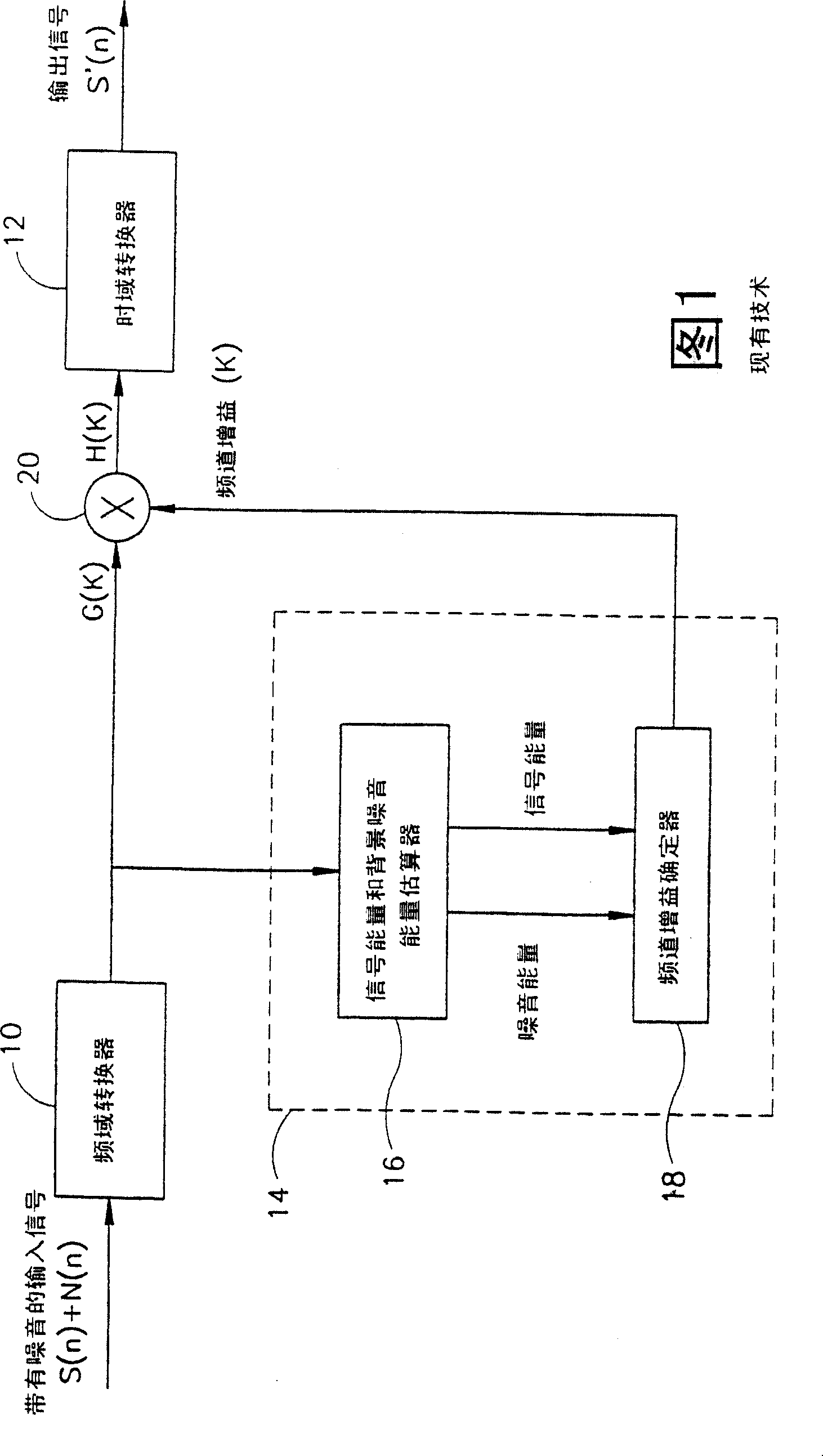
[0033] Reference is now made to FIG. 4 which illustrates a noise suppressor having weighted gain smoothing characteristics constructed and operative in accordance with a preferred embodiment of the present invention. The present invention adds a weighted gain smoother 30, designated 14 in FIG. 1, to the noise attenuator. The same reference numerals denote the same parts.

[0034] Weighted gain smoother 30 receives channel gain γ produced by channel gain determiner 18 ch (i), and smooth the gain values ​​for each channel. The output of smoother 30 is a smoothing gain for the i-th channel of time-domain frame m It is supplied to multiplier 20 .

[0035] Applicants have realized that for signals with low SNR, the channel gain determiner 18 does not correctly estimate the channel gain γ ch (i), the inappropriate judgments it makes cause fluctuations that lead to musical noise. The weighted gain smoother 30 of the present invention uses previous gain values ​​to smooth the ga...


PUM


Abstract

A noise suppressor comprising: a signal-to-noise ratio (SNR) determiner (16), a channel gain determiner (18), a gain smoother (30) and a multiplier (20). A signal-to-noise ratio (SNR) determiner determines the signal-to-noise ratio of each channel of the input signal; a channel gain determiner determines the channel gain γ of each i-th channel ch (i); the gain smoother produces a smoothing gain for each ith channel; the multiplier multiplies each channel of the input signal by its associated smoothing gain.

Description

[0001] This application is a divisional application with application number 99807717.8 and titled "A Noise Suppressor with Weighted Gain Smoothing Feature" submitted on June 15, 1999. technical field [0002] The present invention generally relates to methods of noise suppression by reducing the sound spectrum. Background technique [0003] In speech communication systems, the purpose of audio noise suppression is generally to improve the overall quality of the desired audio or speech signal by filtering out ambient background noise from the desired speech signal. This method of speech enhancement is especially desirable in environments with unusually high background noise. [0004] Referring now to FIG. 1, there is shown a noise suppressor employing spectral reduction (or spectral gain modification). The present noise suppressor comprises frequency domain and time domain converters 10 and 12, and a noise attenuator 14, respectively. [0005] This frequency domain converte...

Claims


Application Information

Patent Timeline
Patent Type & Authority Patents(China)
IPC IPC(8): H04B15/00G10L21/02G10L19/02H04B1/10
CPCG10L21/0208
Inventor 拉斐尔·扎克
Owner D S P C TECH
Why Eureka
Try Eureka