A push rod

A push rod and anchor rod technology, which is applied to the push rod field of filler tools, can solve the problems of increased assembly and maintenance costs, embedded surface damage, production loss, etc., and achieves the effect of reducing the number of push rods broken

Active Publication Date: 2009-03-04
BRAUN AG
View PDF6 Cites 0 Cited by
  • Summary
  • Abstract
  • Description
  • Claims
  • Application Information

AI Technical Summary

Problems solved by technology

[0005] Actually the point now is that when the borehole is no longer aligned with the longitudinal axis of the push rod, i.e. when the borehole is inclined relative to this longitudinal axis, so that the bristle tufts not only no longer protrude perpendicularly from the surface of the toothbrush head, And there is a certain angle of inclination, which has the disadvantage that the embedded surface is often damaged or even the end of the push rod is broken off
This results in a significant increase in assembly and repair costs as the push rod needs to be removed from the filler tool, trimmed and reshaped
No other brush heads can be filled during this time, so significant production loss

Method used


Image

  • A push rod
  • A push rod
  • A push rod

Examples


Embodiment Construction

[0020] At the outset it should be noted that a device for embedding a retaining element in a bore of a brush head by means of a push rod is known from DE 195 28 762 C1 and EP 1 088 495 A1 and has been described in great detail in the above two articles describe them. Therefore, no further description is necessary at this point. The disclosures in both applications should be incorporated by reference into this application.

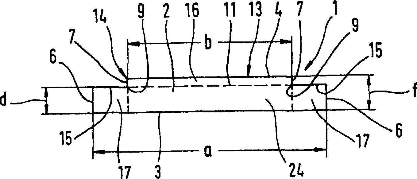
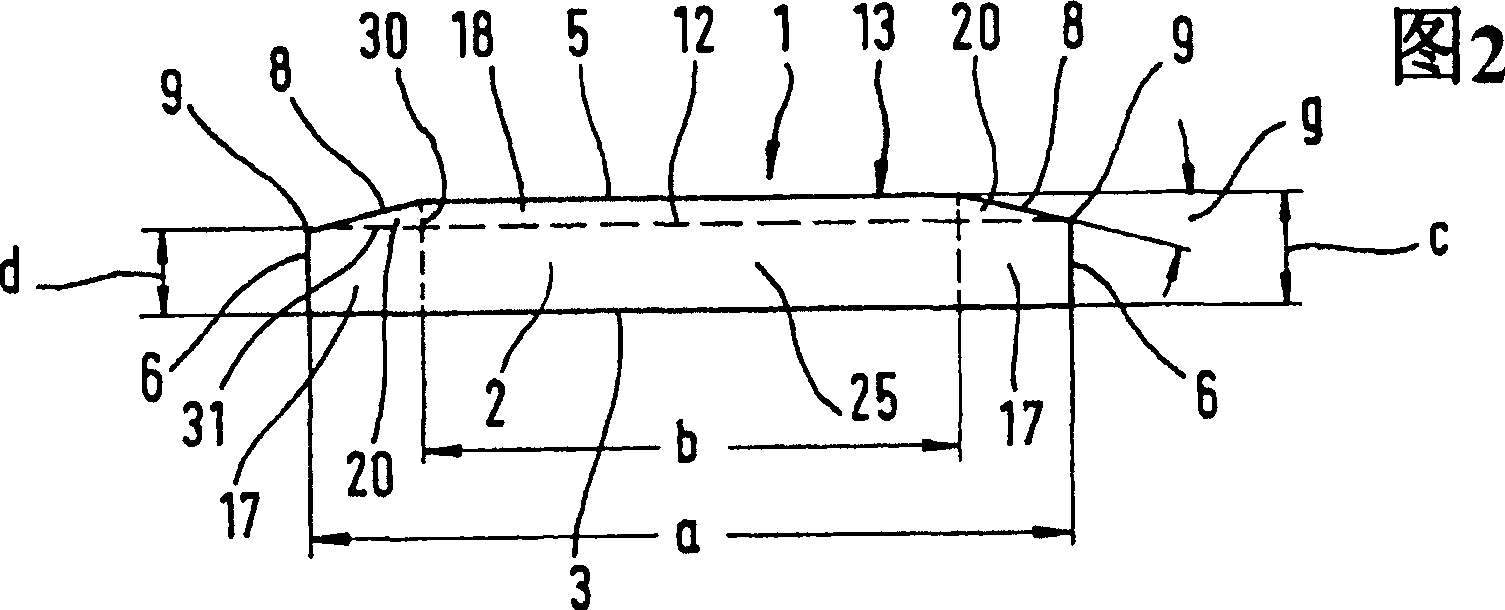
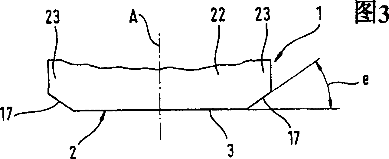
[0021] Therefore only illustrate the innovative design of push rod 1 below, it is in figure 1 , 2 and 4 are represented by embedded surface 2. In Figure 3 the push rod 1 is shown along the Figure 4 Lateral cross-sectional view in the X direction. The longitudinal axis A of the push rod 1 in Fig. 3 corresponds to that in DE 195 28 762 C1 figure 1 , 5 and 9 and are designated by the same reference numerals, ie the plunger 1 extends vertically upwards according to FIG. 3 , but its embedded surface 2 is perpendicular to the drawing plane.

[0022] exist ...


PUM


Abstract

The invention relates to a push rod ( 1 ) of a filler tool according to EP 1088495 A1 for inserting a strip-shaped holding element, preferably an anchor rod, into a bristle tuft-accommodating pore of a brush head. The push rod (1) has an engagement surface (2) on the end side for engagement of the holding element, its cross section (3, 4, 15; 3, 5, 8; 3) consists of a longitudinal face and an end face (6, 7; 6, 8; 6, 10) are limited. The push rod ( 1 ) has end regions ( 17 , 20 , 21 ) on the front side, which are penetrated into the material of the brush head when the retaining element is inserted. According to the invention, the cross-sectional area ( 24 , 25 , 26 ) of the push rod ( 1 ) that enters the brush pore and lies outside the end area is wider than the end-side end area ( 17 ).

Description

technical field [0001] The invention relates to a plunger of a filling tool for inserting a strip-shaped holding element into a bore of a toothbrush head that receives bristle tufts. In this case, the push rod has an insertion surface on the end side for engaging the bolt, the cross section of which is delimited by the longitudinal face and the end face. Background technique [0002] Such a plunger for a filling tool is known from DE 195 28 762 C1. according to figure 1 , 5 and 9, the push rod 30 has a rectangular cross-section, and its thickness corresponds substantially to the figure 1 The separate embedding surfaces of the staples 20 pressed against each other by 5 and 5 are generally referred to as retaining elements or anchor rods hereinafter. In FIG. 9 , the anchor rod 20 is separated by the push rod 30 from the steel band 22 extending perpendicular to the longitudinal axis A of the push rod 30 . The longitudinal axis A of the push rod 30 is parallel to the center ...

Claims


Application Information

Patent Timeline
Patent Type & Authority Patents(China)
IPC IPC(8): A46D3/04
CPCA46D3/042
Inventor 乔治斯·德里森沃尔夫冈古斯·舒佩特米夏埃尔·迪米格
Owner BRAUN AG
Why Eureka
Try Eureka