
Drawer slide rail and its manufacturing method

A manufacturing method and slide rail technology, which are applied to drawers, furniture parts, household appliances, etc., can solve the problems of inapplicable manufacturing cost requirements, large width of non-fixed parts, and low stress on the installation surface, so as to reduce processing errors. , The effect of improving processing quality and saving production costs

Inactive Publication Date: 2009-03-18
何顺辉
View PDF6 Cites 0 Cited by
  • Summary
  • Abstract
  • Description
  • Claims
  • Application Information

AI Technical Summary

Problems solved by technology

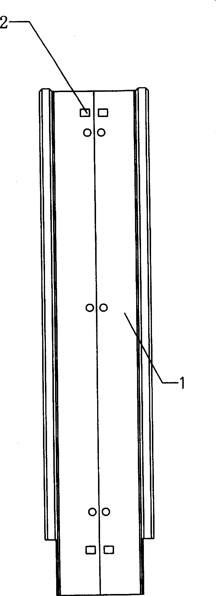
Since the installation surface and the drawer surface are tightly connected when the slide rail is installed, the force on the installation surface is not large during the back and forth sliding process of the slide rail. The traditional processing method of the slide rail obviously wastes the material on the non-fixed part of the installation surface.
Therefore, in the drawer slide rails produced in the prior art, the pull plate 1 has the defect that the width of the non-fixed part is relatively large. More materials are needed, and the production cost is higher
Therefore, the traditional drawer slides are no longer suitable for the existing manufacturing cost requirements

Method used


Image

  • Drawer slide rail and its manufacturing method
  • Drawer slide rail and its manufacturing method
  • Drawer slide rail and its manufacturing method

Examples


Embodiment Construction

[0021] Embodiments of the present invention will be described below with reference to the accompanying drawings.

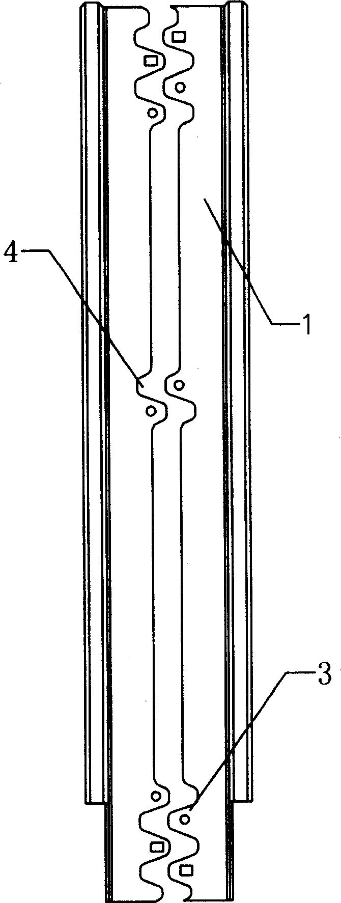
[0022] according to figure 2 As shown in Figure 3, the drawer slide rail of the present invention includes a vertical plate and two pull plates 1, the vertical plate is installed on the inside of the table, the pull plate 1 is sleeved in the vertical plate, and can slide along the vertical plate, and the other end passes through the vertical plate. Screws, nails or rivets secure the drawer. One of the pull plates 1 is provided with a lug 3 for fixing. In order to facilitate the installation of the lug 3, the edges of the lug 3 are rounded. The lug 3 is provided with a mounting hole 2 , and the other pull plate 1 is provided with a recess 4 matching with the lug 3 . In order to ensure the stability of the installation of the pull plate 1 , there are at least two sets of lugs 3 and recesses 4 on any pull plate 1 , and the lugs 3 and recesses 4 are arranged at bot...


PUM


Abstract

Disclosed a slide rail of drawer and its manufacturing method comprises a standing plate, at least two drawplates and a cover of drawplate inside the standing plate and sliding along the standing plate. Wherein, a protruding ear for fixing is mounted on one drawplate, and mounting holes are arranged on said protruding ear while a concave meeting this protruding ear is arranged on another drawplate; each one drawplate at least has two groups of protruding ears and concaves which are mounted on the two ends of drawplate; the middle parts of two drawplates have a group of relative protruding ears and concaves; two drawplates are pressed and molded by the method of cover-cutting which comprises following steps: cutting the blank; incising the bland according to demanded shape and size on the raw material; pressing and bending to be molded as a conjoined unit with left and right drawplates; punching the mounting holes on the mounting surface of the blank according to the demand; separating the left and right drawplates according to the shapes of protruding ear and concave. Said inventive slide rail of drawer and its manufacturing method can save material and reduce the cost.

Description

technical field [0001] The invention relates to a drawer slide rail and a manufacturing method thereof. Background technique [0002] Traditional drawer slide rails usually include a pair of slide rails respectively arranged on both sides of the bottom of the drawer. Such as figure 1 As shown, the slide rail is composed of a vertical plate and a pull plate 1, wherein the vertical plate is installed on the inside of the table; the mounting surface of the pull plate 1 is provided with a mounting hole 2, which is socketed in the vertical plate and can slide along the vertical plate. The mounting surface of the pull plate 1 is tightly connected with the outer surface of the drawer, and the pull plate 1 slides back and forth along the inner wall of the vertical plate to achieve the purpose of opening and closing the drawer. [0003] In the traditional method of processing drawer slide rails, usually the pull plates 1 are processed in pairs. Cut out blanks with corresponding sh...

Claims


Application Information

Patent Timeline
Patent Type & Authority Patents(China)
IPC IPC(8): A47B88/04
Inventor 何顺辉
Owner 何顺辉
Learn More