Liquid crystal display device

A technology of a liquid crystal display device and a liquid crystal display panel, which is applied to static indicators, instruments, etc., can solve problems such as image quality degradation, stroboscopic flickering, difficult user comprehensive image quality improvement, etc., and achieve the effect of comprehensive image quality improvement

Inactive Publication Date: 2009-03-25
SHARP KK
View PDF9 Cites 4 Cited by
  • Summary
  • Abstract
  • Description
  • Claims
  • Application Information

AI Technical Summary

Problems solved by technology

[0023] (2) It can be considered that the visual characteristics when watching moving images have the time integral effect of eyeball movement and vision, and the visual response to the intensity of light stimulation is nonlinear, but the most important tracking movement in eye movement in perceiving moving images (the left and right eyes roughly The characteristics of the same tracking of moving objects) vary depending on the moving speed of the moving object image, and when some image content is displayed with a reduced pulse rate, the above-mentioned stroboscopic defect may occur
[0024] For example, in the case of an image that is moving (full motion) on the full screen in the horizontal direction as in the broadcast of sports such as rugby and volleyball, the image quality degradation due to motion blur is significant, so it is best to reduce the pulse rate as much as possible. In this way, moving image display with reduced motion blur and clear outline can be realized. However, in the case of an image where the person of interest is fixed and the background is moving, reducing the pulse rate will lead to a high possibility of image degradation caused by the above-mentioned stroboscopic defect.
[0025] (3) Moreover, when the pulse rate is reduced, on the opposite side of reducing the motion blur defect of the moving image, the black display time (non-display time of the image) in 1 frame period is increased, so especially in the white image display part Flicker is conspicuous, resulting in deterioration of image quality due to this flicker
[0027] The optimal pulse rate varies depending on the image content, image material, etc., and due to individual differences in users, the sensory sensitivity (dynamic vision) to motion blur, strobe, and flicker varies greatly, so it is difficult to improve the overall image quality for each user. The problem

Method used


Image

  • Liquid crystal display device
  • Liquid crystal display device
  • Liquid crystal display device

Examples


Embodiment approach 1

[0118] below, together with Figure 8 to Figure 10 , to describe Embodiment 1 of the present invention in detail. Here, FIG. 8 is a functional block diagram showing a schematic composition of key parts of Embodiment 1 of the liquid crystal display device of the present invention. Figure 9 It is an explanatory diagram for explaining an example of the basic operating principle of Embodiment 1 of the liquid crystal display device of the present invention. Figure 10 It is an explanatory diagram for explaining another example of the basic operating principle of Embodiment 1 of the liquid crystal display device of the present invention.

[0119] As shown in FIG. 8, the liquid crystal display device of this embodiment has a separation unit 1 and an image decoding unit 2. The former extracts images, voice data, and control data (content information, etc. ) of the input multiplexed data (transport stream) is separated into individual data, and the latter MPEG-decodes the separated ...

Embodiment approach 2

[0154] Next, together with Figure 11 and Figure 12 Embodiment 2 of the present invention will be described; the same parts as those in Embodiment 1 above will be denoted by the same reference numerals, and description thereof will be omitted. here, Figure 11 It is an explanatory diagram for explaining an example of the basic operation principle of the liquid crystal display device of this embodiment, Figure 12 It is an explanatory diagram for explaining another example of the basic operating principle of the liquid crystal display device of this embodiment.

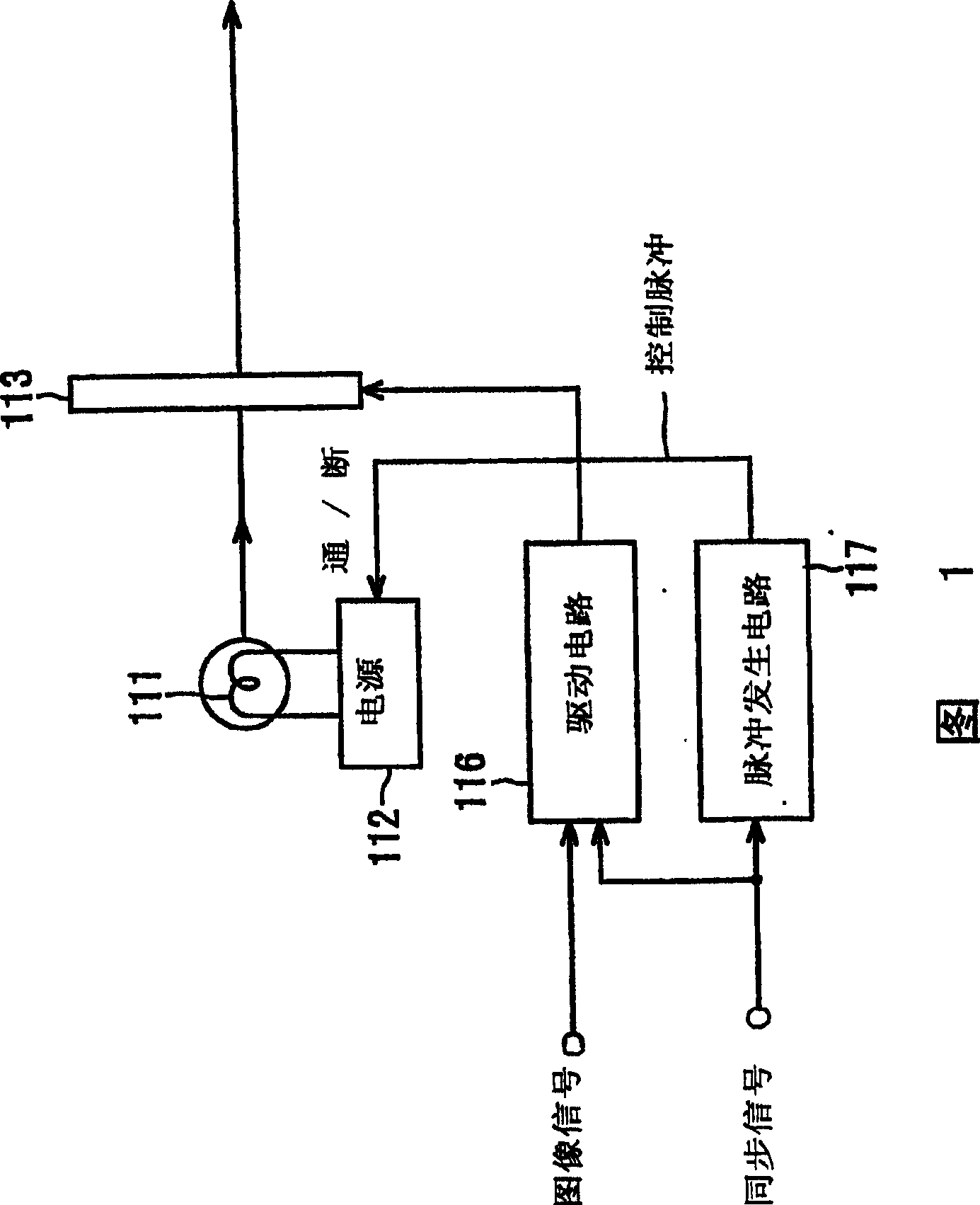
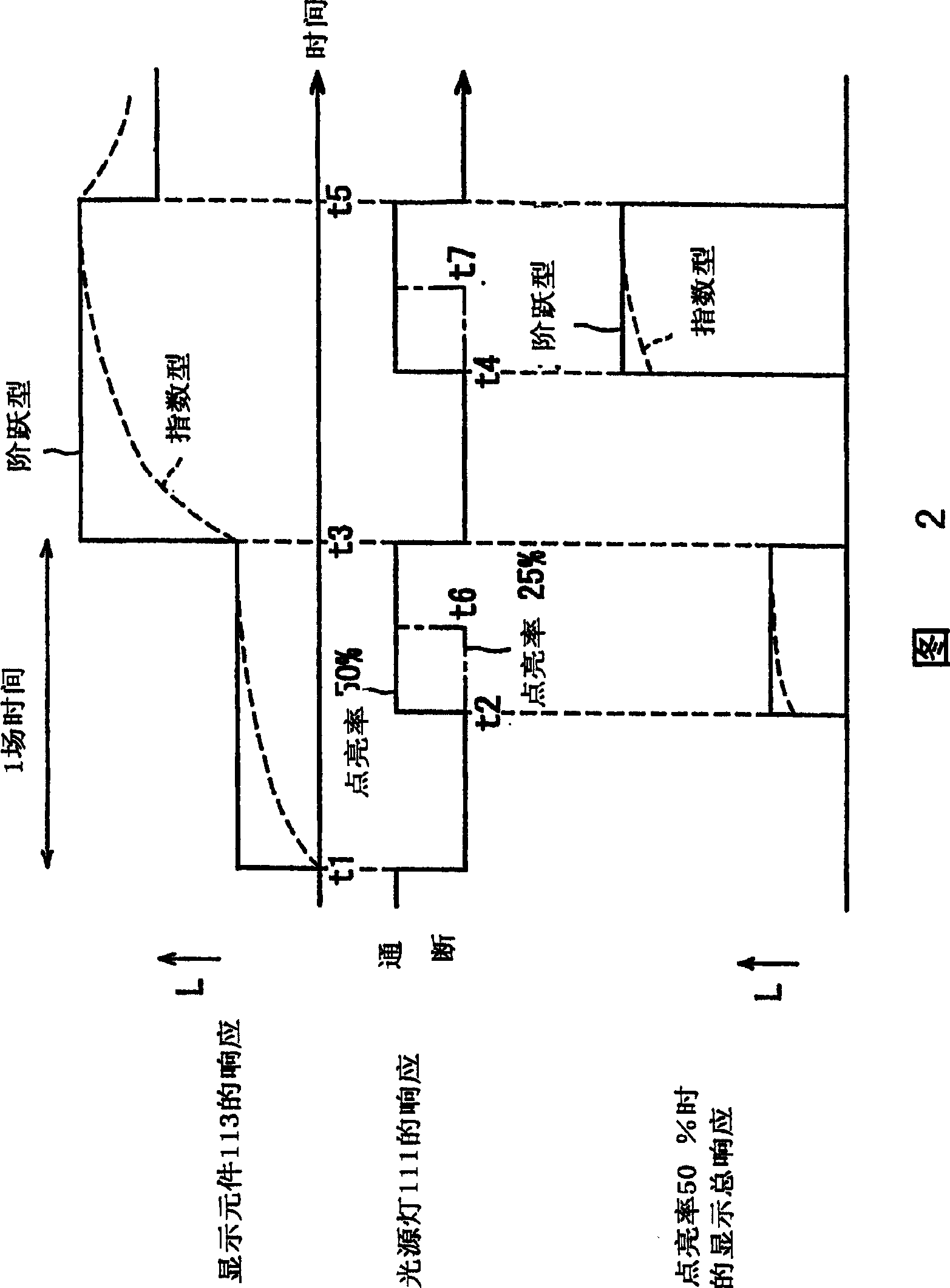
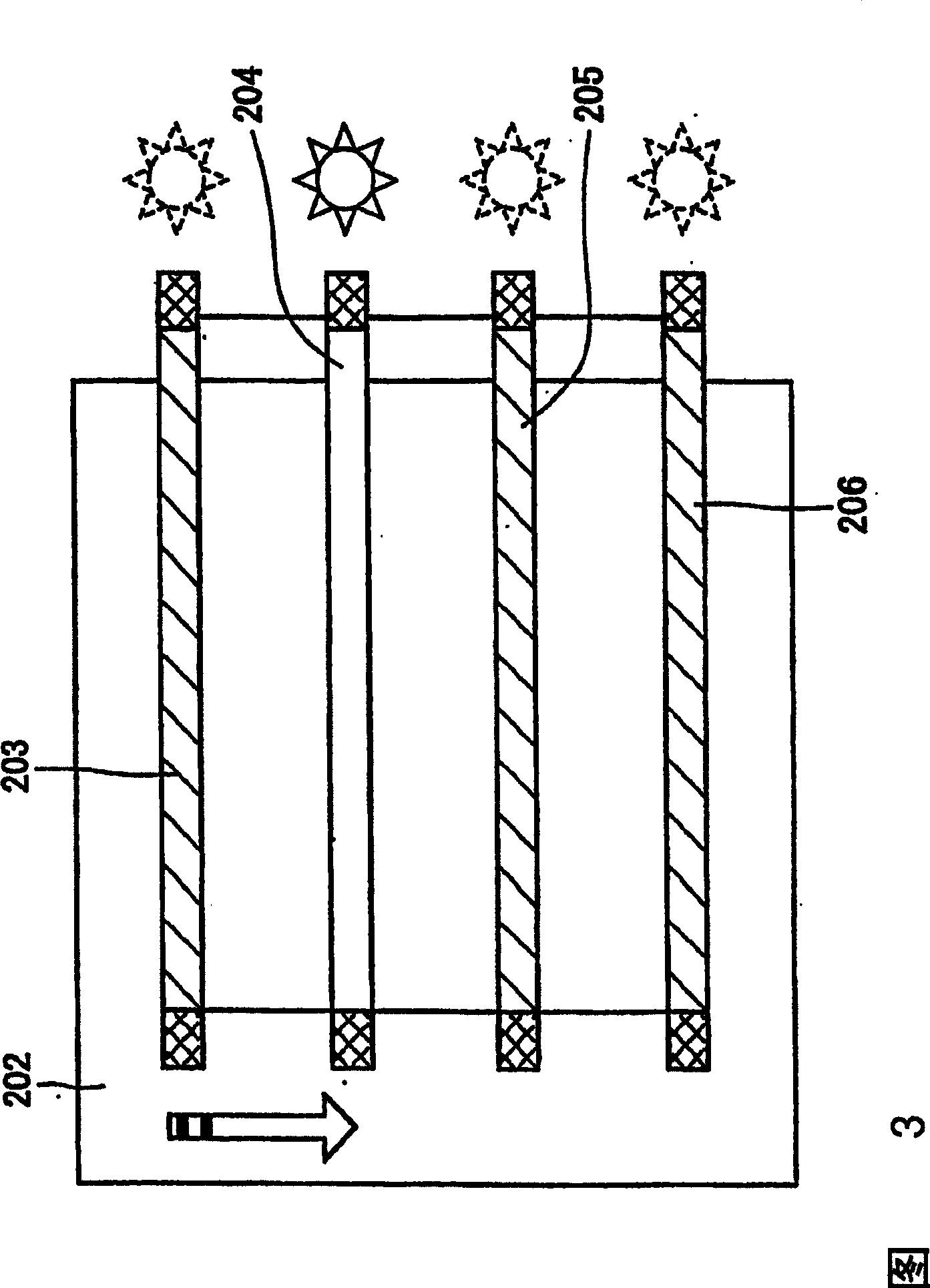
[0155]The liquid crystal display device of the present embodiment prevents motion blur during moving image display by using a scanning backlight lighting method, and its basic functional block diagram is the same as that of the first embodiment described above with FIG. 1 . The difference is that a predetermined number (number) of the backlight light sources 7 composed of a plurality of down-light or side-illuminat...

Embodiment approach 3

[0185] Next, together with Figure 13 to Figure 15 Embodiment 3 of the present invention will be described; the same parts as in Embodiment 2 above will be denoted by the same reference numerals, and description thereof will be omitted. Here, FIG. 13 is a functional block diagram showing a schematic configuration of key parts of the liquid crystal display device of this embodiment, Figure 14 is a timing chart for explaining the electrode driving operation of the liquid crystal display device of this embodiment, Figure 15 It is an explanatory diagram for explaining an example of the basic operating principle of the liquid crystal display device of this embodiment.

[0186] Such as Figure 14 As shown, in the liquid crystal display device of this embodiment, the backlight light source 7 is always on (continuously on), and the image display signal is written and scanned to the liquid crystal display panel 16 within one frame period, followed by a black display signal. The bl...


PUM


Abstract

A liquid crystal display device in which a frame of the image signal to be displayed is written into a liquid crystal display panel (6) while a backlight (7) is activated intermittently within one frame period so as to prevent blur injury arising when displaying motion pictures includes: means (8) and (9) for variably controlling the illumination duration of the backlight (7) based on the detected type of the image content to be displayed. This configuration makes it possible to appropriately control the image quality degradation caused by blur injury, stroboscopic effect and flickering, hence realize total image quality improvement.

Description

technical field [0001] The present invention relates to a liquid crystal display device for illuminating a liquid crystal display panel with a backlight source and displaying images, and more particularly to a liquid crystal display device for preventing motion blur during display of moving images by approaching pulse-type display. Background technique [0002] In recent years, efforts have been made to develop flat-panel display devices (FPD) such as liquid crystal display devices (LCD) that can realize high definition, low power consumption, and space saving. Among them, LCDs are used in computer display devices and television display devices. The popularity is very remarkable. However, in contrast to cathode ray tubes (CRTs), which are primarily used for this purpose, the disadvantage of "motion blur" in LCDs can be pointed out, that is, when a moving image is displayed, the viewer perceives the outline of moving parts to be blurred. [0003] For example, as disclosed in...

Claims


Application Information

Patent Timeline
Patent Type & Authority Patents(China)
IPC IPC(8): G09G3/36G09G3/34G09G3/30
Inventor 杉野道幸吉井隆司藤根俊之
Owner SHARP KK
Why Eureka
Try Eureka