
Shoot error compensating method and device and weapon system computer

A shooting error and computer technology, which is applied to the control system of guns, aiming devices, measuring devices, etc., can solve the problems of large manpower, danger, and time-consuming, and achieve the goal of less time and manpower, accurate shooting error, and reduced risk Effect

Inactive Publication Date: 2009-04-22
OERLIKON CONTRAVES BESCHRAENKTER HAFTUNG
View PDF5 Cites 0 Cited by
  • Summary
  • Abstract
  • Description
  • Claims
  • Application Information

AI Technical Summary

Problems solved by technology

Existing methods cannot measure all types of gun parameters
Measurements also cannot be automated and are therefore time consuming; as a result, only a few measurements can be taken at each measurement location for the weapon gun barrel, so random measurement errors cannot be eliminated
Such measurements are not only time-consuming, but also require a lot of manpower, making the measurements very expensive
In addition, some surveyors must be located in the muzzle area of ​​the weapon gun barrel for measurement work, which is quite dangerous; to measure a gun with a large elevation angle and a long barrel of the weapon gun, the surveyor must use lifting equipment to rise to the bottom of the weapon gun barrel. Can only be measured in the muzzle area of ​​the gun or on the ladder

Method used


Image

  • Shoot error compensating method and device and weapon system computer
  • Shoot error compensating method and device and weapon system computer
  • Shoot error compensating method and device and weapon system computer

Examples


Embodiment Construction

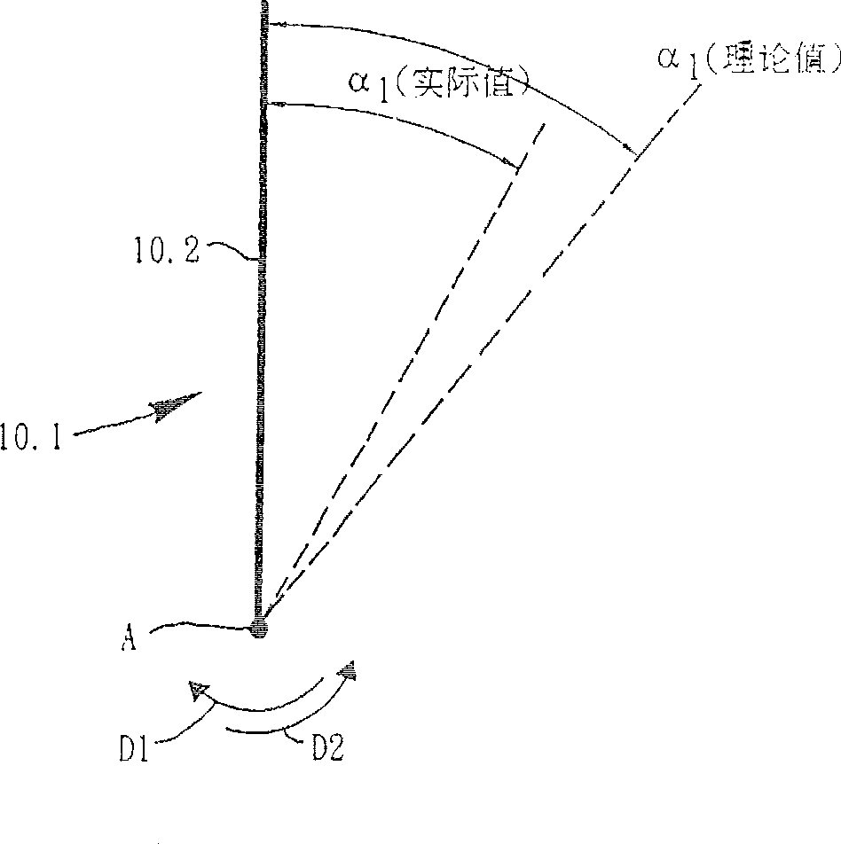
[0076] It is well known that the errors of measurements are small compared to absolute values ​​such as azimuth or elevation, so the graphs representing error curves and error functions are not drawn to scale so that the trend of the function can be clearly seen.

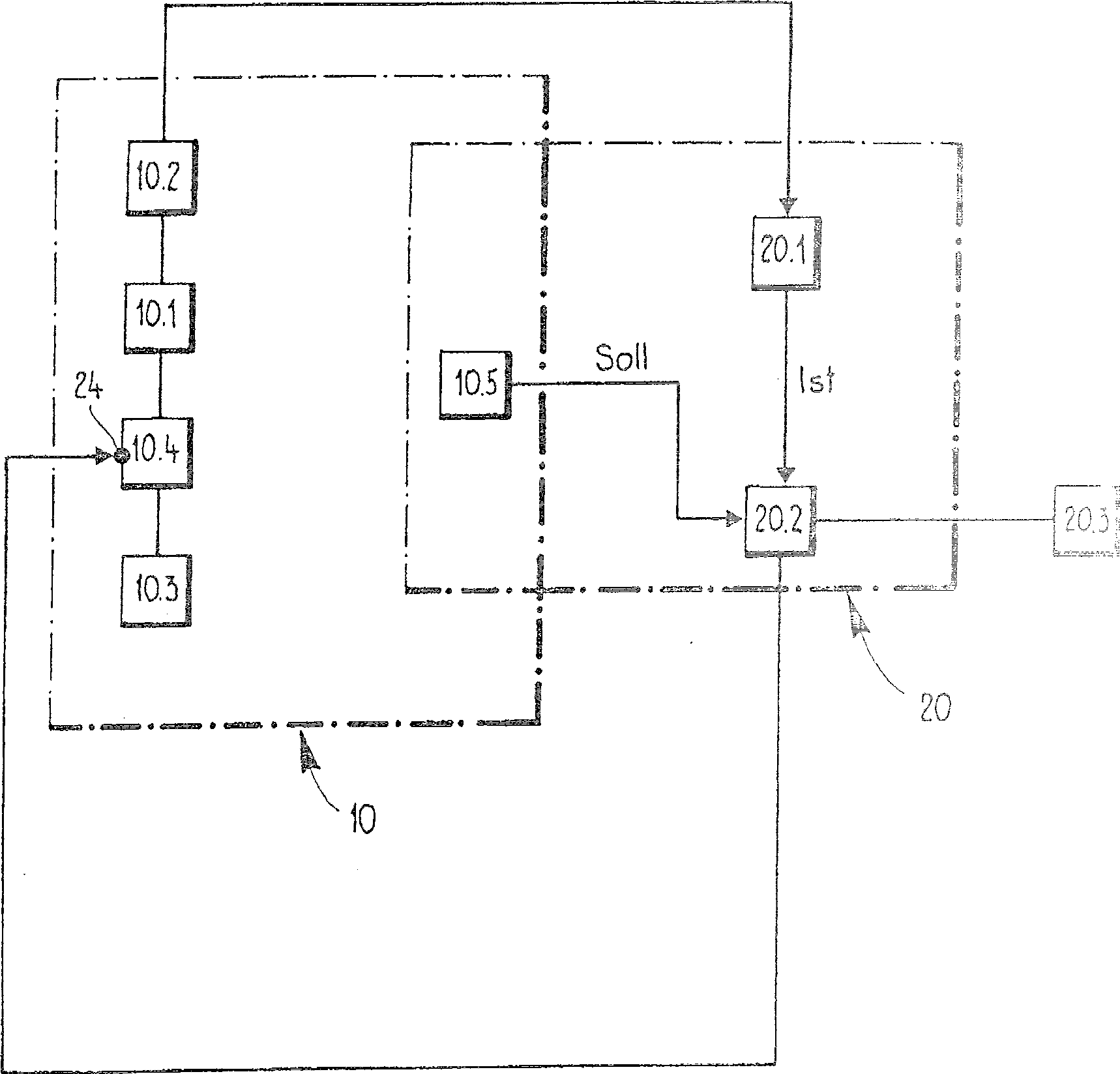
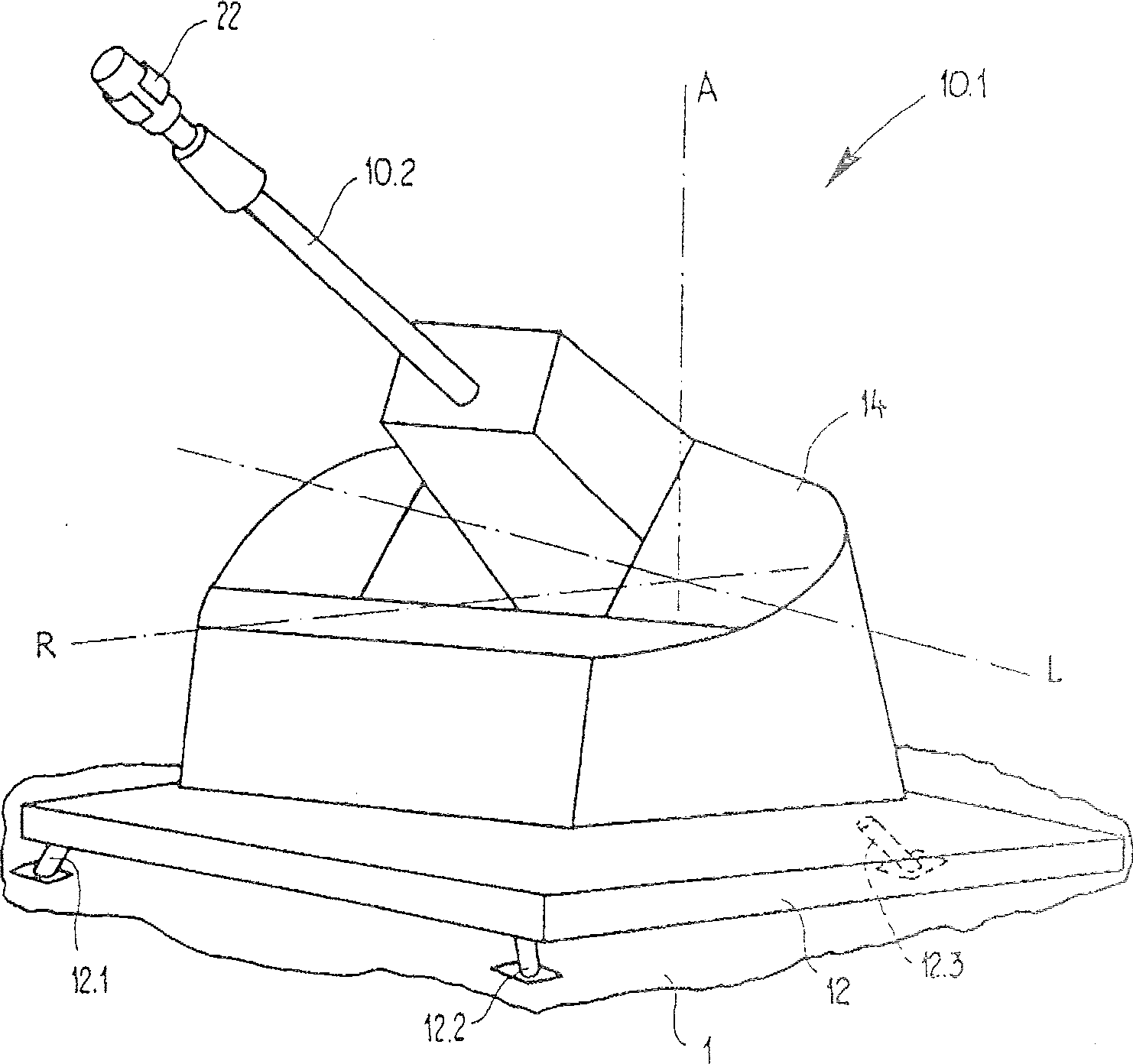
[0077] Figure 1A Shown is weapon system 10 in diagrammatic representation. The weapon system 10 is equipped with a gun 10.1 with a weapon barrel 10.2, a firing adjustment device 10.3 and a firing adjustment computer and / or system computer 10.4. The weapon system 10 is also provided with a preset value detector 10.5 for detecting the preset position of the barrel 10.2 of the weapon gun.

[0078] also, Figure 1A An apparatus 20 for carrying out the method of the invention is shown. The device 20 is provided with a measuring device 20.1 for determining the actual value describing the actual position of the gun barrel 10.2 of the weapon after aiming, and a calculator 20.2. The predetermined value detector 10 . 5 i...


PUM


Abstract

A method and a device (20) are described for compensating firing errors of a gun having a weapon barrel (10.2). Firing errors, which are caused by static gun geometry errors, which influence the position of the weapon barrel (10.2) during aiming of the weapon barrel (10.2) at aiming values, are compensated. For this purpose, the weapon barrel (10.2) is brought into measurement positions in steps by rotation around an axis. Using suitable devices of a measurement facility, an intended value, which describes the intended position of the weapon barrel (10.2), and an actual value, which describes the actual position of the weapon barrel (10.2), are detected at each measurement position. A difference between the actual value and the intended value, defined as an error value, is then calculated. Correction values are established from multiple error values of the measurement positions and the correction values are taken into consideration during later aiming of the weapon barrel (10.2). The method and the device (20) are used for a weapon system (10) which has a system computer (10.4) for calculating aiming values for aiming a weapon barrel (10.2) of a gun (10.1) of the weapon system (10); the system computer (10.4) has a data input (24) for data which is made available, this data being intended for the purpose of being taken into consideration during the calculation of the aiming values, in order to compensate aiming errors, which are caused by static gun geometry errors and which influence the position of the weapon barrel (10.2).

Description

(1) Technical field [0001] The invention relates to a method and device for compensating shooting error of a gun with a barrel of a weapon gun in a weapon system, and the shooting error is caused by a geometric error of a static gun; and a system computer for a weapon system. (2) Background technology [0002] Firearms consist of many individual parts which are rigidly or flexibly connected to each other. The dimensional accuracy of these individual parts cannot be manufactured very precisely, but has a certain manufacturing tolerance and / or deviation compared with the theoretically determined size, and a fixed assembly tolerance that deviates from the predetermined position relative to each other occurs during assembly. The total deviation causes each gun to have a certain deviation from the ideal geometry, which is called the gun geometric error. Such gun geometric errors consist of many kinds of errors. For example, the geometric error of the gun shows that the azimuth ...

Claims


Application Information

Patent Timeline
Patent Type & Authority Patents(China)
IPC IPC(8): F41G1/54F41A27/30F41G3/32G01C19/00
CPCF41G3/323F41G5/26F41A27/30
Inventor G·施奈德M·格伯U·迈耶
Owner OERLIKON CONTRAVES BESCHRAENKTER HAFTUNG
Learn More