

Image display apparatus for writing display information with reduced electric consumption
An image display device and a technology for displaying information, applied to static indicators, instruments, identification devices, etc., can solve the problem of unnatural viewers
- Summary
- Abstract
- Description
- Claims
- Application Information
AI Technical Summary
Problems solved by technology
Method used
Image

Examples
Embodiment 1
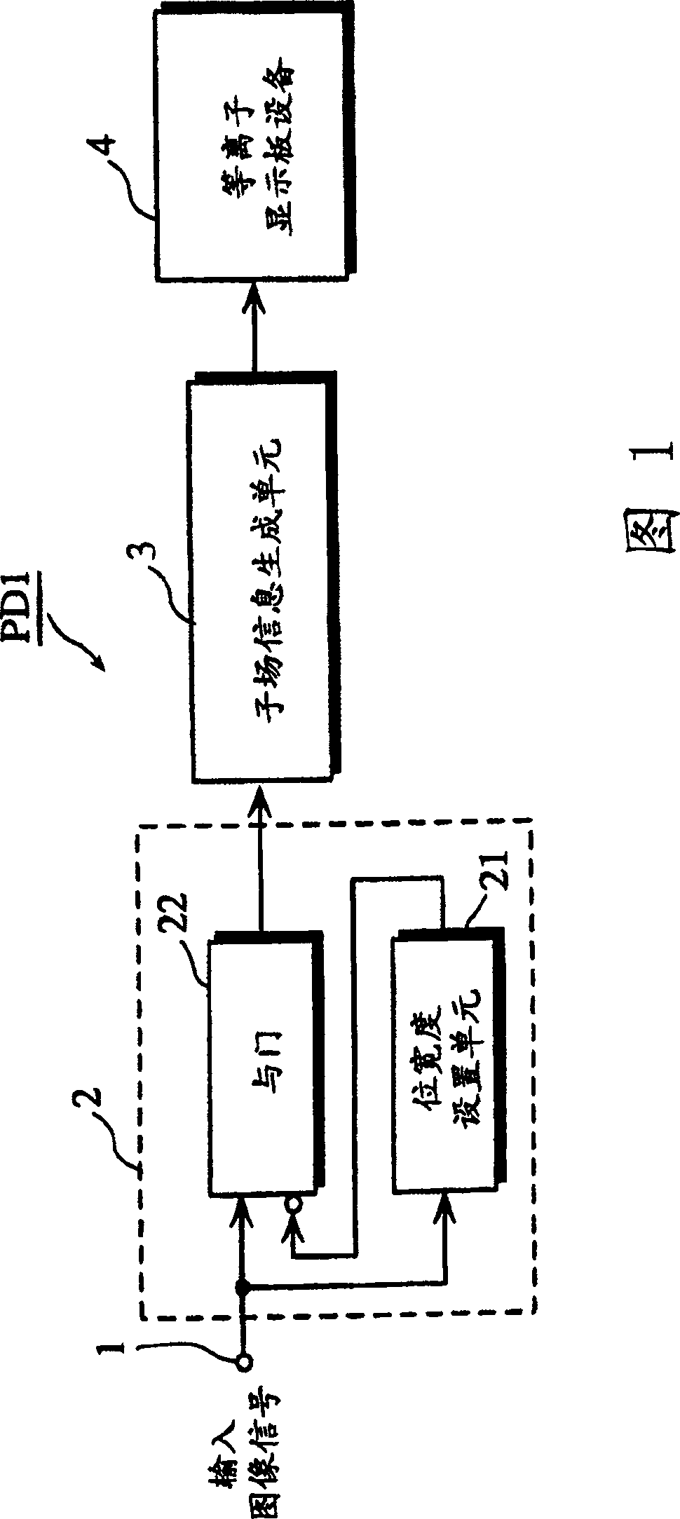
[0083] Figure 1 shows a block diagram of the structure of a plasma display PD1 using subfields to display grayscale images.
[0084] As shown in FIG. 1 , the plasma display PD1 includes an input image signal conversion unit 2 , a subfield information generation unit 3 , and a plasma display panel device 4 .
[0085] The input image signal conversion unit 2 includes a bit width setting unit 21 and an AND gate 22 .
[0086] The subfield information generating unit 3 converts an image signal supplied from the input image signal converting unit 2 into segments of on / off information (ie, subfield information). Here, the input image signal includes various gray scales for displaying pixels constituting one image on one screen. Each on / off information segment or subfield information represents a combination of a set of subfields corresponding to one of the gray levels. Each subfield is allocated in advance with a luminance weight. Light emission is maintained with a brightness wei...
Embodiment 2
[0103] A plasma display PD2 of the second embodiment of the present invention will be described, focusing on the differences from the first embodiment.
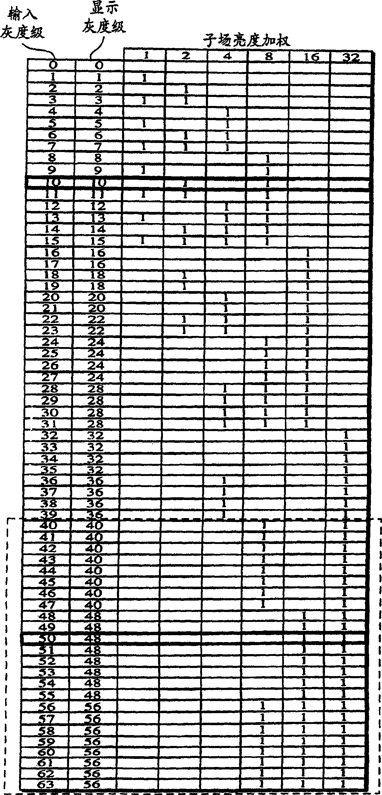
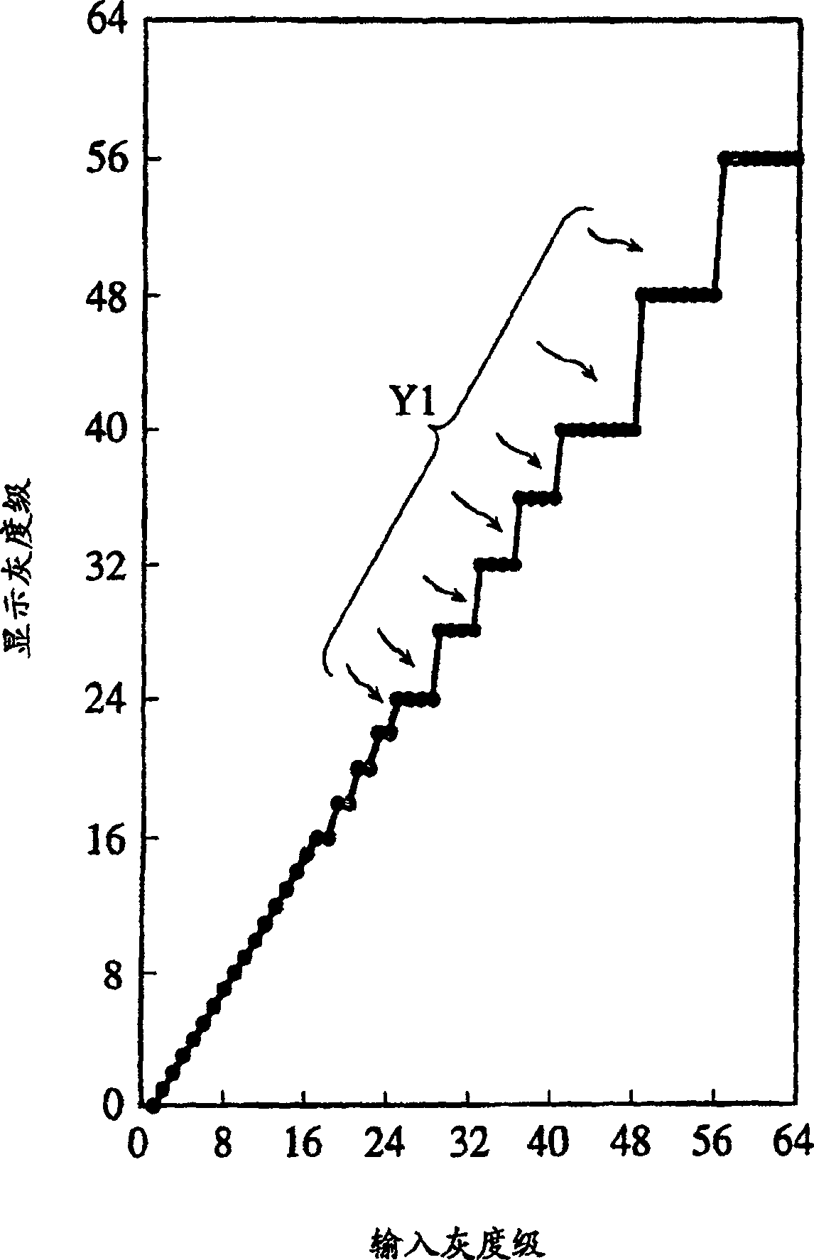
[0104] FIG. 4 shows the relationship between the gray scales contained in the input image signal and the gray scales used for displaying the image in the case of the plasma display PD2. In other words, FIG. 4 shows the relationship between the input and the output of the input image signal conversion unit 2 shown in FIG. 1 . Figure 5 Shown on the vertical axis vs. grayscale levels displayed. A curve with input grayscale levels on the horizontal axis.
[0105] In this embodiment, the lower bits are intentionally fixed to "1" as the gray level decreases.
[0106] For example, when an image signal with a gray level "10" (subfield information for the input value is "001010") is input, the output gray level is also "10" (the subfield information for the output value is "10"). The subfield information is "001010"). That is, sin...
Embodiment 3
[0112] A plasma display PD3 according to a third embodiment of the present invention will be described, focusing on differences from Embodiments 1 and 2.
[0113] FIG. 6 shows the relationship between the gray scale contained in the input image signal and the gray scale used to display the image in the case of the plasma display PD3. In other words, FIG. 6 shows the relationship between the input and output of the input image signal conversion unit 2 shown in FIG. 1 . Figure 7 shows a curve of the displayed gray level on the vertical axis vs. the input gray level on the horizontal axis.
[0114] In this embodiment, the lower bits are intentionally fixed to "0" as the gray level decreases. But for a group of input gray levels close to the maximum gray level, the input gray levels are output when they are displayed as gray levels.
[0115] For example, when an image signal with a gray level of "10" (the subfield information for the input value is "001010") is input, the outpu...
PUM
 Abstract
Description
Claims
Application Information