Optical imaging system and target simulation system

An optical imaging system and smooth surface technology, applied in the optical field, can solve the problems of low image resolution, low reliability, and small display area, so as to improve resolution, ensure contrast and brightness uniformity, and ensure consistency Effect

Active Publication Date: 2018-06-12
XIAN MICROMACH TECH CO LTD
View PDF4 Cites 4 Cited by
  • Summary
  • Abstract
  • Description
  • Claims
  • Application Information

AI Technical Summary

Problems solved by technology

[0004] The embodiment of the present invention provides an optical imaging system and a target simulation system, aiming to solve the problems of low image resolution, small display area, chromatic aberration, large volume and low reliability in the prior art

Method used


Image

  • Optical imaging system and target simulation system
  • Optical imaging system and target simulation system
  • Optical imaging system and target simulation system

Examples


Embodiment 1

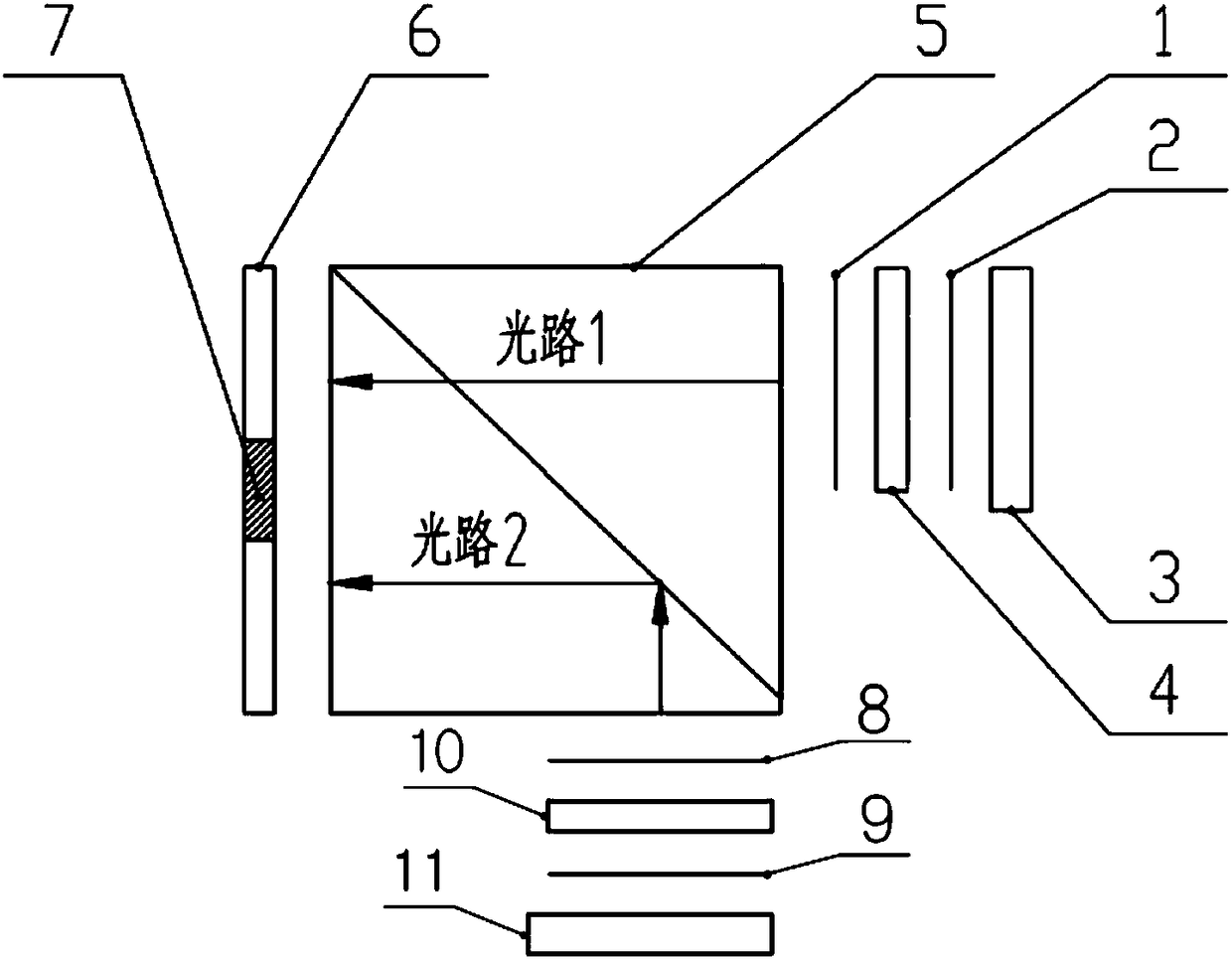
[0023] figure 1 A specific structural block diagram of the optical imaging system provided by Embodiment 1 of the present invention is shown, and for convenience of description, only parts related to the embodiment of the present invention are shown. In this embodiment, the optical imaging system includes: a polarization splitting device 5, a micro display module 6, a first polarized light source module and a second polarized light source module; The bonding part of the rectangular prism forms a light-splitting surface; the micro-display module 6 is spliced ​​by two identical micro-displays; Adjacent to the equivalent focal plane, wherein, the P light of the first polarized light source module enters the polarization beam splitting device 5 vertically and completely passes through the beam splitting surface, and the S light of the second polarized light source module enters the polarization beam splitting device 5 vertically , and is reflected on the splitting surface at an a...

Embodiment 2

[0035] The target simulation system provided by Embodiment 2 of the present invention includes: a dual-channel control board and the optical imaging system described in Embodiment 1, the dual-channel control board is electrically connected to the optical imaging system, and is used to directly drive the optical imaging system miniature display module.

[0036] In this embodiment, one driver main board is used to drive two micro-displays, which ensures the consistency of the contrast and brightness uniformity of the two micro-displays.

Embodiment 3

[0038] The implementation flow of the splicing method for microdisplays provided by Embodiment 3 of the present invention is described in detail as follows:

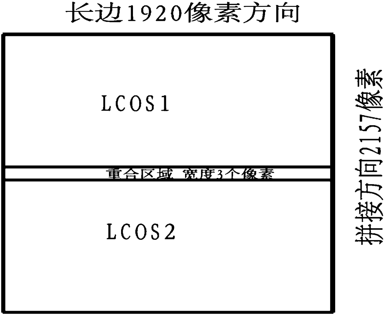
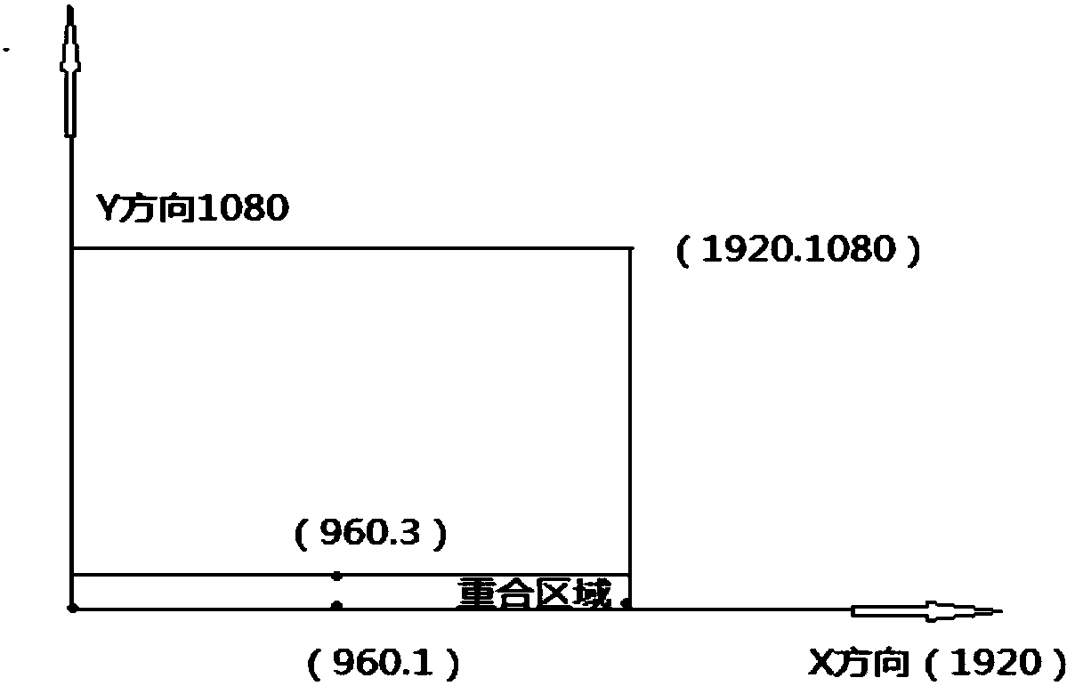
[0039] Such as figure 1 , 2 As shown, the second liquid crystal light valve 10 is installed on the optical platform, and the position of the first liquid crystal light valve 4 is adjusted using a six-dimensional precision turntable, so that the pixels that need to be overlapped are completely overlapped to meet the splicing accuracy requirements. At the same time of fine-tuning, it is necessary to set the second liquid crystal light valve 10 as a benchmark, and another piece of first liquid crystal light valve 4 is fine-tuned relative to the second liquid crystal light valve 10. The equipment used includes six-dimensional precision moving platform, two-dimensional moving platform, parallel Light pipe and theodolite. Stitching on the short side (1080 direction) has 3 pixels for coincidence accuracy, so the effective lig...


PUM


Abstract

The invention is suitable for the optical technology field and provides an optical imaging system and a target simulation system. The system comprises a polarization light splitting device, a miniature display module, a first polarized light source module and a second polarized light source module, wherein the polarization light splitting device is formed through gluing one pair of rectangular prisms, and a light splitting surface is formed at the bonding position of the rectangular prisms; the miniature display module is formed through splicing two same miniature displays; the first polarizedlight source module and the second polarized light source module are arranged on two adjacent equivalent focal planes of the polarization light splitting device; the P light of the first polarized light source module is vertically emitted into the polarization light splitting device and completely passes through the light splitting surface; the S light of the second polarized light source moduleis vertically emitted into the polarization light splitting device and is reflected at a 45 degree angle on the light splitting surface; the emitting directions of the S light and the P light form a 90 degree angle; and the P light and the S light finally generate an image in the miniature display module. In the invention, through an optical splicing technology, the resolution of the optical imaging system is increased, simultaneously, the size of the optical imaging system is reduced and weight is mitigated.

Description

technical field [0001] The invention belongs to the field of optical technology, in particular to an optical imaging system and a target simulation system. Background technique [0002] At present, with the continuous improvement of the optical imaging system, the requirements for the dynamic target simulation module are getting higher and higher, and the demand for high resolution, small pixels, and large display area is becoming more and more obvious. However, the most commonly used resolution at present is : 1920X1080, because the optical field of view of the lens is circular, the available resolution can only be 1080 pixels. The current resolution affects the overall performance of the optical system. At the same time, most of the micro-display devices used in China are imported from abroad, which are generally effective The aspect ratio of the display area is a rectangle of 16:9. Since the optical field of view is circular, there are less usable parts. For this reason,...

Claims


Application Information

Patent Timeline
Patent Type & Authority Applications(China)
IPC IPC(8): G02B27/28
CPCG02B27/28
Inventor 胡加杰杨小君王华高宇王晓腾
Owner XIAN MICROMACH TECH CO LTD
Why Eureka
Try Eureka