Black matrix forming method, display module and display device
A display module and black matrix technology, applied in identification devices, instruments, vacuum evaporation coating, etc., can solve the problems of low precision, thick thickness, etc., achieve low light transmittance, ensure the effect of light output and contrast
- Summary
- Abstract
- Description
- Claims
- Application Information
AI Technical Summary
Problems solved by technology
Method used
Image
Examples
Embodiment 1
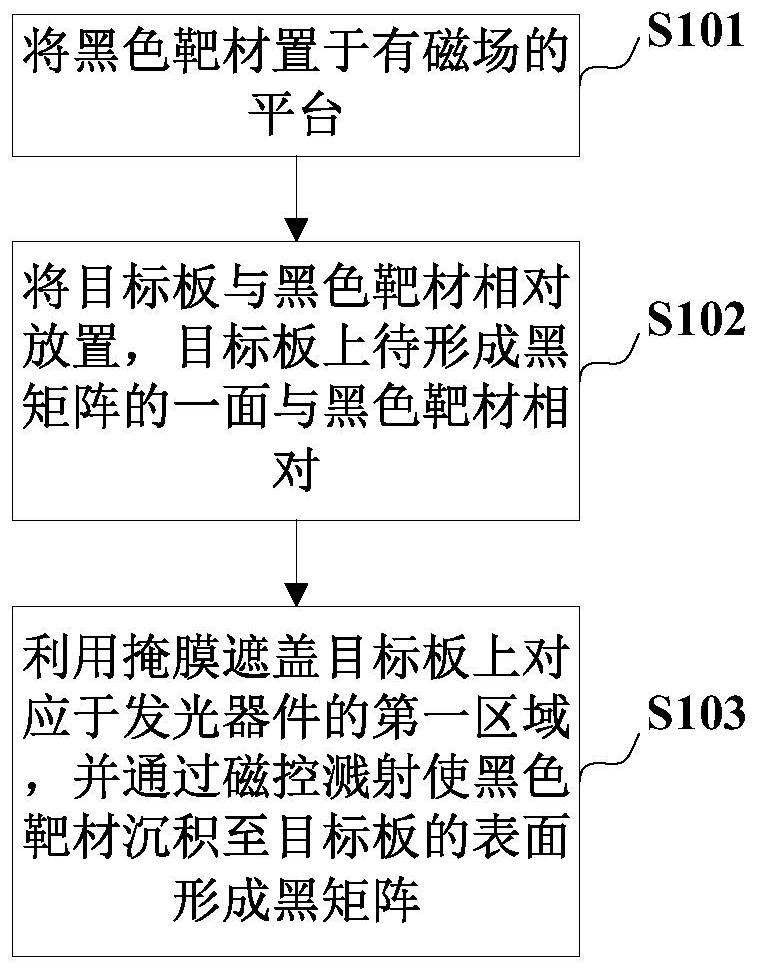
[0056] In order to solve the problems that the black matrix formed by the traditional black matrix forming method is relatively thick and the precision is not high. This embodiment provides a black matrix forming method, please refer to figure 1 , the black matrix forming method includes:
[0057] S101, placing the black target on a platform with a magnetic field;
[0058] S102, placing the target board and the black target material opposite to each other, and the side of the target board to be formed with the black matrix is opposite to the black target material;
[0059] S103, using a mask to cover the first region corresponding to the light emitting device on the target board, and depositing a black target material on the surface of the target board by magnetron sputtering to form a black matrix.
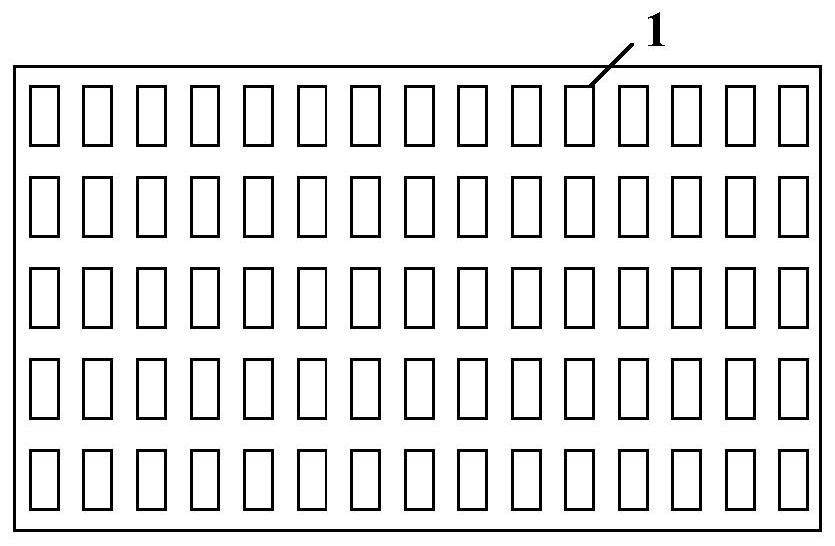
[0060]The black target is the material used to form the black matrix, including but not limited to carbon black, metal light-absorbing materials and other materials that can ...
Embodiment 2
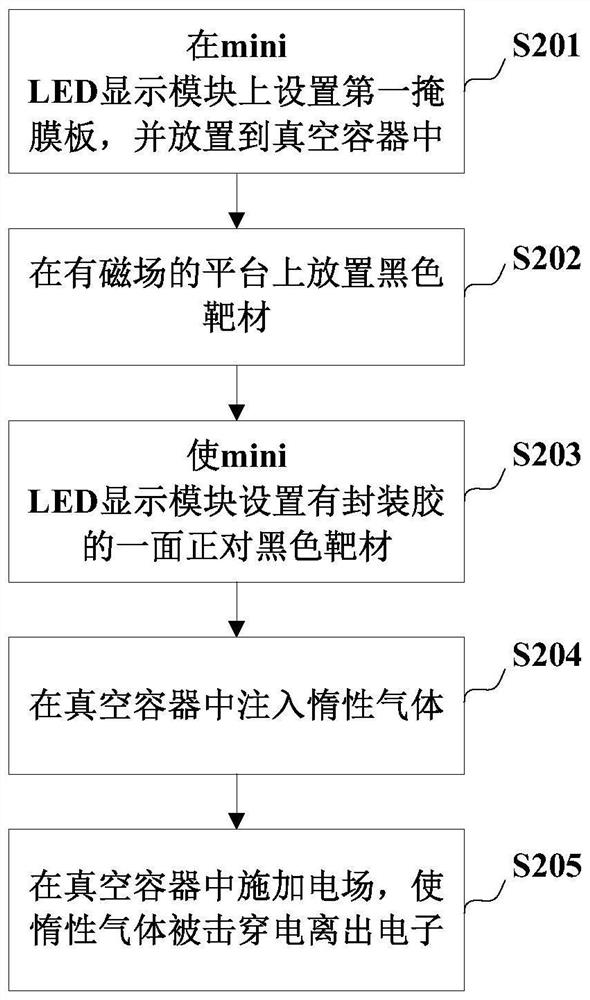
[0087] In order to better illustrate the black matrix forming method of the present invention, this embodiment will be further described in conjunction with the accompanying drawings and the specific forming process, please refer to image 3 , is a detailed flow chart of the black matrix forming method provided in this embodiment. In this embodiment, the target board is taken as an example of a mini LED display module. The mini LED display module includes a substrate, an array of light-emitting devices arranged on the substrate, and an encapsulant for encapsulating and protecting the light-emitting devices. In this embodiment, Among them, the light-emitting device specifically includes a mini LED chip. In the following example of this embodiment, a black matrix is formed on the packaging glue of the mini LED display module.
[0088] S201, setting a first mask plate on the mini LED display module, and placing it in a vacuum container;
[0089] Such as Figure 4 , the first ...
Embodiment 3
[0114] This embodiment provides a display module, which includes a black matrix, and the black matrix is formed by using the black matrix forming method exemplified in Embodiment 1 and Embodiment 2. Exemplarily, the black matrix can be formed on the substrate including but not limited to the display module, the packaging glue of the display module, and the cover plate of the display module. The display module may include but not limited to mini LED display module, OLED display module, micro LED display module, etc.
[0115] This embodiment provides a display device, which includes the above-mentioned display module. The display device provided in this embodiment can be applied to various lighting fields, for example, it can be applied to various display fields (which can be televisions, monitors, terminals such as mobile phones), the display module may include, for example, an LED display panel, a mini LED display panel, a micro LED display panel, and the like. The above-me...
PUM
| Property | Measurement | Unit |
|---|---|---|
| thickness | aaaaa | aaaaa |
| transmittivity | aaaaa | aaaaa |
Abstract
Description
Claims
Application Information
 - R&D
- Intellectual Property
- Life Sciences
- Materials
- Tech Scout
- Unparalleled Data Quality
- Higher Quality Content
- 60% Fewer Hallucinations
Browse by: Latest US Patents, China's latest patents, Technical Efficacy Thesaurus, Application Domain, Technology Topic, Popular Technical Reports.
© 2025 PatSnap. All rights reserved.Legal|Privacy policy|Modern Slavery Act Transparency Statement|Sitemap|About US| Contact US: help@patsnap.com


